Does anyone have a dwg or cross-section of the Festool Guide Rail?

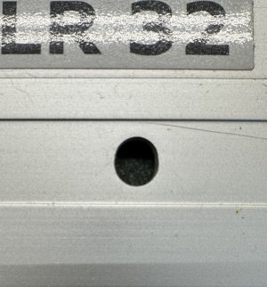
I am not 100% certain of the diameter of the holes/ sprung pin.....My LR32 rails are in my work workshop, so I dont have access to them at the moment.

The elongation of the holes is left/right as you run the jig along the rail.
Obviously, the tolerance of the pin as it fits into the hole as the jig proceeds along the rail, is snug but the width of the elongated hole allows for the very slight adjustments.
 
I’ve had the question of “What thickness of nut will slide in that ceiling-facing track?”

A long time ago I posted a series of photos on here with different nuts and bolts that fit the Festool Guide Rail. Sorry, I am a bit too lazy right now to search for it, but I find I use the following 2 nuts quite regularly for this.

M6 T-nut for EU20 Profile:

Festool_Guide_Rail_with_M6_T-nut_for_EU20_Profile.jpg

M8 T-nut with Spring:

Festool_Guide_Rail_with_M8_T-nut_with_Spring.jpg
 
The pin on the LR 32 is 5.88 to 5.90 mm Ø. The punched obround holes on the rail are 6.00 x 7.00 mm. The 7 mm width runs across the width of the rail and not the length of the rail.
 
I think the reason the hole is longer across the rail is because the rail is aluminum and the LR sled is steel. The difference in thermal response of the two materials would make the pin bind in a round hole at higher and lower temperatures than whatever the temperature was when the parts where manufactured.
 
Back
Top