smorgasbord
Member
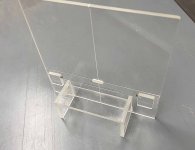
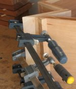
I built a V2 of the jig today:
[attachimg=1]
Changes from the previous version:
• Base plate is larger (200mm square)
• Built-in foot to hold the Domino vertically square
• Alignment marks cut with 20º Vee bit on bottom and edges
• Left-Right indexing adjustable via small brass screws
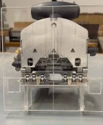
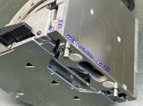
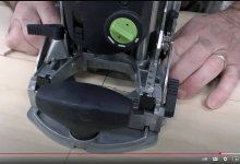
Here's a head on shot (POV of the face being mortised):
[attachimg=2]
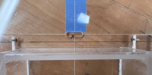
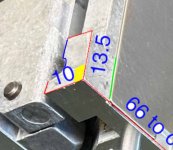
Here's how you align it - same as before except now there's enough plate to clamp:
[attachimg=3]
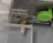
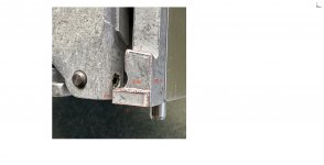
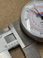
The horizontal (left-right) and indexing turned out to be an issue, in terms of making this to fit more than just my particular instance. If you look closely at the base/fence sides, turns out they're not milled to be in the same plane at all. Even the bottom of the base protrudes a bit from the milled area, and both of those are different from the actual fence that rotates 90º:
[attachimg=4]
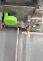
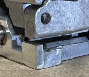
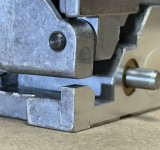
As you can see, I ended up cementing a piece of plexi with a small brass screw in it. That screw head registers against the portion of the base that's milled for the fixed 15mm height (10mm on the DF500), which is recessed from the bottom of the base as well as from the swinging fence portion. I had to size and position the block to not obscure the domino centerline. Here's the other side:
[attachimg=5]
As best I can determine, this is the most accurate way to index the cutter. The distance is 131mm on the DF700, btw. The use of screws lets you adjust not only dead center, but how tight the Domino fits in the jig. Because of the base protrusions, you have the slide the Domino in perpendicular to the face/jig, not slide it along the jig base plate.
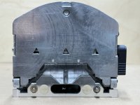
Also relevant is that the bottom base (the plate with the two threaded holes) also isn't all at the same level. The main part, with the center and paddle centerlines, sticks out a tiny bit more than the sides do. And since those centerlines are very accurate, I decided to index the built-in foot against only that part of the base - so making it slightly less wide (only 119mm) than the whole base (which is well over 120mm)
Finally, I cut the alignment marks with a narrow 20º Vee bit and didn't see the need to ink fill them. They're cut on the bottom only, so parallax is practically nothing. And cutting alignment marks on the edges as well is a big help. A raking light into the jig's sides makes those marks stand out quite clearly, btw.
These changes make the jig more stable and less complicated to use (no external foot needed), as well as accommodated small variations in fence assembly size, in case Festool manufacturing over the years has changed slightly.
I don't have a DF500, but the main change would be that the foot is located 10mm off the horizontal centerline instead of 15mm. I think the fence/base widths are the same. If someone has a DF500 and can confirm:
• Width of bottom of base excluding the cast sides is 119mm
• Width between the milled areas that show the 10mm centerline is 131mm
• I will also need the distance off the centerline (or off the base bottom) for where the screwheads should go. On the DF700 there is 15mm of area there, but the DF500 should have only 10mm, with the bottom few mm sticking out more and appearing rough. So I would assume that putting the head such that it doesn't go beyond 10mm, but is very close, is the best location.
I've also decided to stick with the nominal ¼" plexiglass. That measures 5.5mm in thickness, which I think is absolutely fine for face mortising where going too deep would be really bad, so ½ mm less deep is actually a feature, especially if other Dominos are like mine and cut almost a mm deeper than the depth setting. I think anything less than 5.7mm thick but at least 5mm would be fine.
In terms of manufacturing (should I go that route), I think the process would be to cut a 200mm square blank on the CNC to ensure squareness, then rout the alignment Vee grooves, then flip over and rout shallow dados for the foot assembly to ensure alignment. I'd still need to rout the alignment marks on the sides by hand (router table probably) and then cut and assemble the foot assembly, then glue up. Instead of gluing the foot assembly in place, perhaps pre-drilling for screws on the CNC would be less stressful than the glue-up. Thoughts anyone?
I built this prototype with a tablesaw, 5-cut tweaked cross-cut sled, and router table. Both tablesaw and router table have fence DROs. I struggled a bit with the foot assembly since I didn't do the dado thing for alignment, but that operation probably needs the CNC or router table/template jigging to be accurate and repeatable.
[attachimg=1]
Changes from the previous version:
• Base plate is larger (200mm square)
• Built-in foot to hold the Domino vertically square
• Alignment marks cut with 20º Vee bit on bottom and edges
• Left-Right indexing adjustable via small brass screws
Here's a head on shot (POV of the face being mortised):
[attachimg=2]
Here's how you align it - same as before except now there's enough plate to clamp:
[attachimg=3]
The horizontal (left-right) and indexing turned out to be an issue, in terms of making this to fit more than just my particular instance. If you look closely at the base/fence sides, turns out they're not milled to be in the same plane at all. Even the bottom of the base protrudes a bit from the milled area, and both of those are different from the actual fence that rotates 90º:
[attachimg=4]
As you can see, I ended up cementing a piece of plexi with a small brass screw in it. That screw head registers against the portion of the base that's milled for the fixed 15mm height (10mm on the DF500), which is recessed from the bottom of the base as well as from the swinging fence portion. I had to size and position the block to not obscure the domino centerline. Here's the other side:
[attachimg=5]
As best I can determine, this is the most accurate way to index the cutter. The distance is 131mm on the DF700, btw. The use of screws lets you adjust not only dead center, but how tight the Domino fits in the jig. Because of the base protrusions, you have the slide the Domino in perpendicular to the face/jig, not slide it along the jig base plate.
Also relevant is that the bottom base (the plate with the two threaded holes) also isn't all at the same level. The main part, with the center and paddle centerlines, sticks out a tiny bit more than the sides do. And since those centerlines are very accurate, I decided to index the built-in foot against only that part of the base - so making it slightly less wide (only 119mm) than the whole base (which is well over 120mm)
Finally, I cut the alignment marks with a narrow 20º Vee bit and didn't see the need to ink fill them. They're cut on the bottom only, so parallax is practically nothing. And cutting alignment marks on the edges as well is a big help. A raking light into the jig's sides makes those marks stand out quite clearly, btw.
These changes make the jig more stable and less complicated to use (no external foot needed), as well as accommodated small variations in fence assembly size, in case Festool manufacturing over the years has changed slightly.
I don't have a DF500, but the main change would be that the foot is located 10mm off the horizontal centerline instead of 15mm. I think the fence/base widths are the same. If someone has a DF500 and can confirm:
• Width of bottom of base excluding the cast sides is 119mm
• Width between the milled areas that show the 10mm centerline is 131mm
• I will also need the distance off the centerline (or off the base bottom) for where the screwheads should go. On the DF700 there is 15mm of area there, but the DF500 should have only 10mm, with the bottom few mm sticking out more and appearing rough. So I would assume that putting the head such that it doesn't go beyond 10mm, but is very close, is the best location.
I've also decided to stick with the nominal ¼" plexiglass. That measures 5.5mm in thickness, which I think is absolutely fine for face mortising where going too deep would be really bad, so ½ mm less deep is actually a feature, especially if other Dominos are like mine and cut almost a mm deeper than the depth setting. I think anything less than 5.7mm thick but at least 5mm would be fine.
In terms of manufacturing (should I go that route), I think the process would be to cut a 200mm square blank on the CNC to ensure squareness, then rout the alignment Vee grooves, then flip over and rout shallow dados for the foot assembly to ensure alignment. I'd still need to rout the alignment marks on the sides by hand (router table probably) and then cut and assemble the foot assembly, then glue up. Instead of gluing the foot assembly in place, perhaps pre-drilling for screws on the CNC would be less stressful than the glue-up. Thoughts anyone?
I built this prototype with a tablesaw, 5-cut tweaked cross-cut sled, and router table. Both tablesaw and router table have fence DROs. I struggled a bit with the foot assembly since I didn't do the dado thing for alignment, but that operation probably needs the CNC or router table/template jigging to be accurate and repeatable.