Overtime
Member
- Joined
- Jan 25, 2007
- Messages
- 265
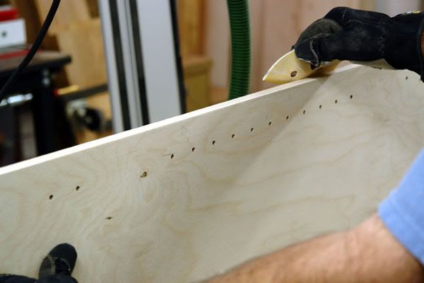
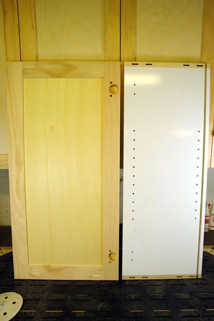
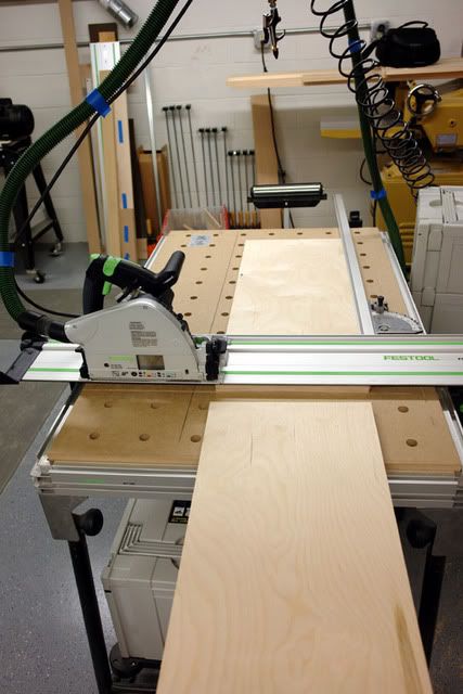
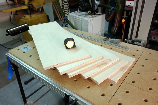
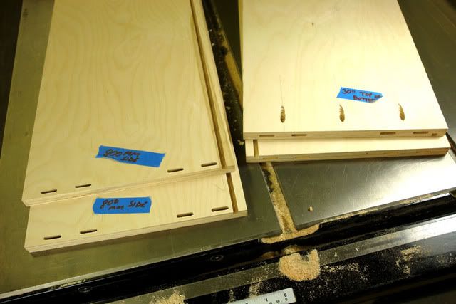
OK. Lets get right into it and make some 32 mm Frameless Cabinets with some Festools.
But, first some Primers and other valuable resources on the subject. First up is Mirko's thread LR 32-SYS Secrets explained.http://festoolownersgroup.com/index.php?topic=452.0
-a must read, as the very "DNA" of the subject is in his opening post. Also http://32mm.dalrun.com/ is another very good read. Danny Proulux's book, Building Frameless Kitchen Cabinets, is yet another great "Fast track" to an end product.
After you complete those go tohttp://www.blum.com/us/en/01/30/index.php and read up on concealed hinges with a focus on Clip top and Clip Hinges, and Mounting plates. Download the Concealed Hinge Brochure- 11mb - 90 pages of hinge hardware. Or just go with Clip downloads to keep it simple. Look at the charts carefully as they will instruct as to proper hinge selection. It's easier than learning Sketch UP. We will need to know what hardware we will be using and how to select it.
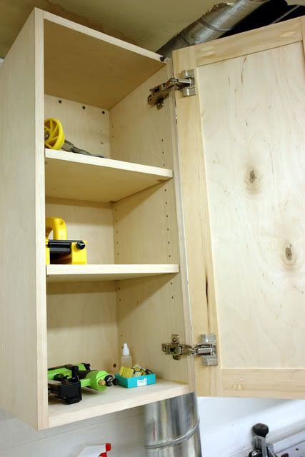
Doesn't matter if you use Blum or not, the hinge brochure is a wealth of knowledge for those of us new to this hardware and its applications. OK wrap your mind around all that Concealed Hinge stuff. To lighten the load, forget about all the angle and specialty hinges for now, don't want to blow a fuse. For this application I will be using Full Overlay hinges for 3/4" stock- this makes the hinge selection more narrow and manageable. All we need to decide on now is the swing angle (how far will the door swing open ?) 107 110 120 170 deg and so on. We will use 120 deg Self Close (because we will be using "soft close pistons." More on that later) fully adjustable hinges. And now we need a mounting plate, Oh no another 1000 choices ! But we know we are going to have full overlay doors so you already know we need 0mm mounting plates. And yes we want cam adjustability. Why, because we may need to tweak things a bit, and having the built in availability to do that is a good thing. Yes it will add a few cents to the hardware expense. OK that was easy.
Here we go: wait we forgot to decide how we want to mount them... with screws, what screws? dowels?
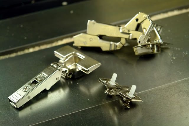
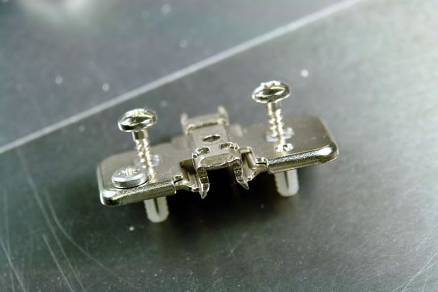
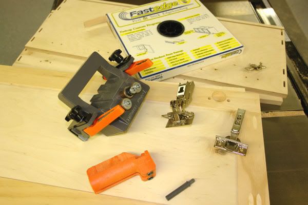
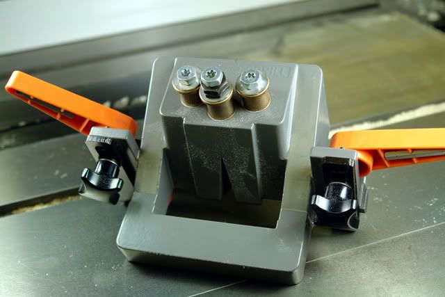
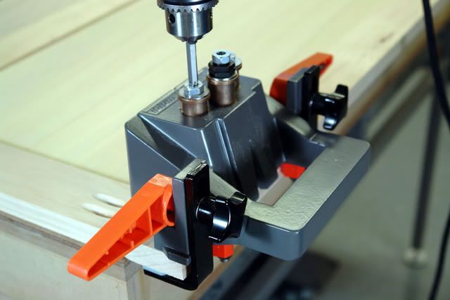
Oh no, more choices ! Yes more. So we finally settled on some hinges and we have two here, the one on the left is a 120 deg full overlay - Blum #71T5590 Self Close Inserta and a 170 deg (high $ because of the full swing open) #71T6540 Self close Inserta. No screws needed for these as the cup expands and locks into place when you press the flap down. These hinges have full toe in toe out and camber adjustmets (not your grandpa's hinges here.) Yes, they will hold tight. And we have a cam adjustable mounting plate #173H710 that comes with the 5mm dowels with screws in place ready to go as shown. We will need 2 hinges and 2 mounting plates per door. And since we will not be buying them by the gross, case, pallet, Lb or Truck Load we can expect to pay about $2.10 ea for the 120 deg hinge and $0.49cents ea for the mounting plates. The 170 deg hinges jump to the $5.00 ea range.
More to come... Wow we haven't even plugged in a tool yet !
But, first some Primers and other valuable resources on the subject. First up is Mirko's thread LR 32-SYS Secrets explained.http://festoolownersgroup.com/index.php?topic=452.0
-a must read, as the very "DNA" of the subject is in his opening post. Also http://32mm.dalrun.com/ is another very good read. Danny Proulux's book, Building Frameless Kitchen Cabinets, is yet another great "Fast track" to an end product.
After you complete those go tohttp://www.blum.com/us/en/01/30/index.php and read up on concealed hinges with a focus on Clip top and Clip Hinges, and Mounting plates. Download the Concealed Hinge Brochure- 11mb - 90 pages of hinge hardware. Or just go with Clip downloads to keep it simple. Look at the charts carefully as they will instruct as to proper hinge selection. It's easier than learning Sketch UP. We will need to know what hardware we will be using and how to select it.
Doesn't matter if you use Blum or not, the hinge brochure is a wealth of knowledge for those of us new to this hardware and its applications. OK wrap your mind around all that Concealed Hinge stuff. To lighten the load, forget about all the angle and specialty hinges for now, don't want to blow a fuse. For this application I will be using Full Overlay hinges for 3/4" stock- this makes the hinge selection more narrow and manageable. All we need to decide on now is the swing angle (how far will the door swing open ?) 107 110 120 170 deg and so on. We will use 120 deg Self Close (because we will be using "soft close pistons." More on that later) fully adjustable hinges. And now we need a mounting plate, Oh no another 1000 choices ! But we know we are going to have full overlay doors so you already know we need 0mm mounting plates. And yes we want cam adjustability. Why, because we may need to tweak things a bit, and having the built in availability to do that is a good thing. Yes it will add a few cents to the hardware expense. OK that was easy.
Here we go: wait we forgot to decide how we want to mount them... with screws, what screws? dowels?
Oh no, more choices ! Yes more. So we finally settled on some hinges and we have two here, the one on the left is a 120 deg full overlay - Blum #71T5590 Self Close Inserta and a 170 deg (high $ because of the full swing open) #71T6540 Self close Inserta. No screws needed for these as the cup expands and locks into place when you press the flap down. These hinges have full toe in toe out and camber adjustmets (not your grandpa's hinges here.) Yes, they will hold tight. And we have a cam adjustable mounting plate #173H710 that comes with the 5mm dowels with screws in place ready to go as shown. We will need 2 hinges and 2 mounting plates per door. And since we will not be buying them by the gross, case, pallet, Lb or Truck Load we can expect to pay about $2.10 ea for the 120 deg hinge and $0.49cents ea for the mounting plates. The 170 deg hinges jump to the $5.00 ea range.
More to come... Wow we haven't even plugged in a tool yet !
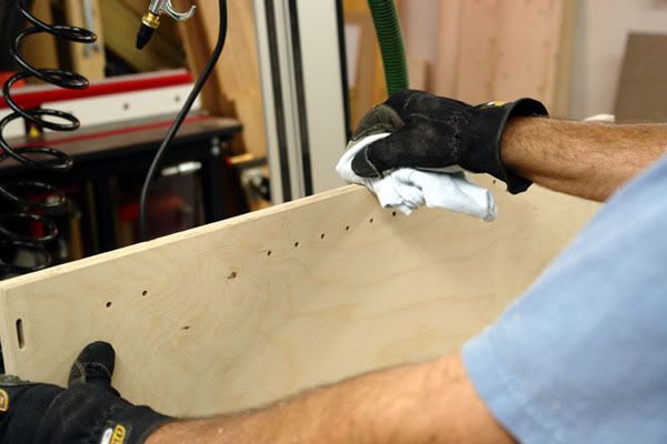
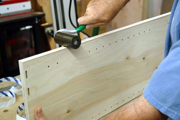
 and that adds time to the finishing dept.
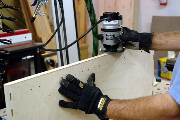
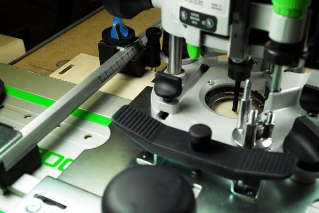
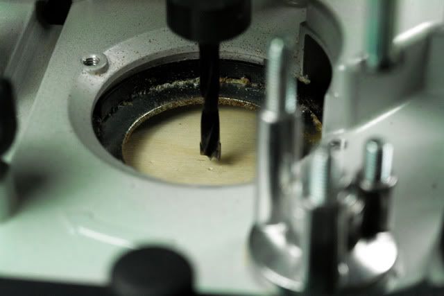
") and OF 1010 EQ router.
and OF 1010 EQ router.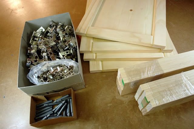

 ect.
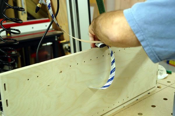
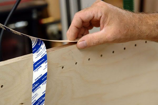
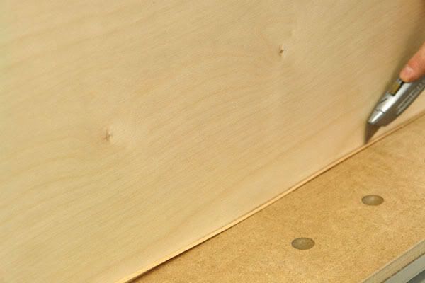
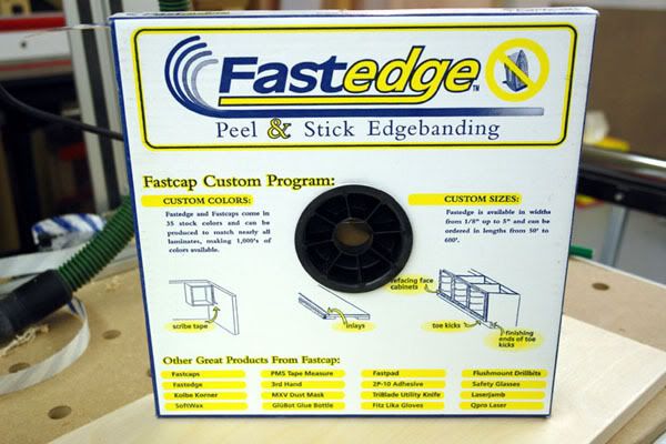
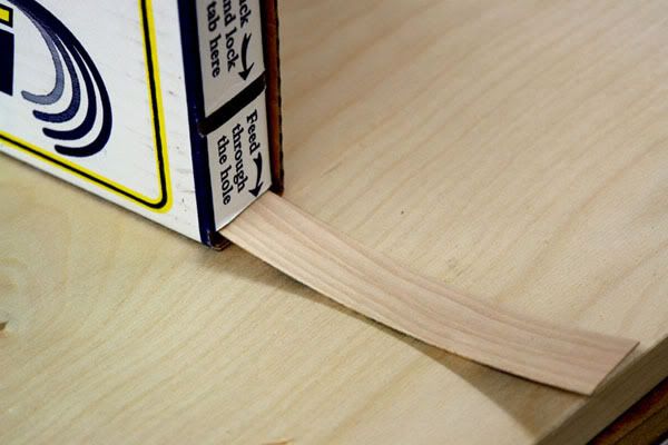
ect.") We will need some good sharp scissors to rough cut our wood tape. We'll cut them each about 1" or so longer then actual size.
We will need some good sharp scissors to rough cut our wood tape. We'll cut them each about 1" or so longer then actual size.