Frank Pellow
Member
- Joined
- Jan 16, 2007
- Messages
- 2,742
(part 1 of 2)
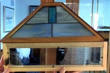
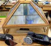
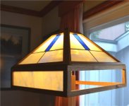
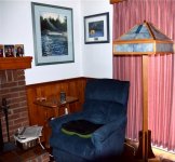
Last year I made a lamp shade utilizing stained lass, oak, and walnut and gave the shade to my wife, Margaret, for Christmas. I promised to make the base ASAP.
Here is a photo of that lampshade under our tree:
[attachthumb=#1]
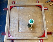
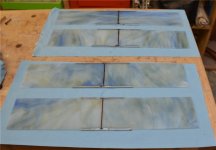
The lampshade plan was for a table lamp but I thought that I could easily extend the plan to make a floor lamp base. So, in January, I made a prototype base out of scrap wood but it didn’t seem right. Somehow, the in extending the table lamp base to a floor lamp base then proportions got out of whack; so I set the project aside. As with so many things that I set aside, it was not until many months later that I got back to it. This time I decided to make a base using a floor lamp plan that I found in Wood magazine. (The plan for the shade came from Fine Woodworking.)
[attachthumb=#3]
The rough quarter-sawn white oak that I put into my work shed to acclimatize a year ago:
[attachthumb=#2]
is certainly now well acclimatized. [smile]
Before I get started, I should explain that, by mistake, I left my MFT at Pellow’s Camp [crying] when closing up last September. So, now my MFT is 1,000 kilometres away and some tasks that would have been done utilizing that table and either a track saw or router will have to be done using other tools.
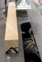
I planed the boards I am using on my new Hammer jointer-planer combo. But, rather than using the jointer to make a square edge, I prefer to use my Festool track saw equipped with a Panther blade for ripping:
[attachthumb=#4] [attachthumb=#5]
Using the same saw, I ripped a the 33 millimetre board that had just been jointed into a couple of pieces approximately 65 millimetres wide. These pieces will later be glued together to form the floor lamp’s column. Once these boards have been glued together, I will trim the column to be 60 millimetres square.
Next, I routed a channel wide enough to hold a 3/8 inch threaded rod in the inside centre of both the column boards:
[attachthumb=#6]
The rod fits well:
[attachthumb=#7]
The short piece of rod that came with the standard lamp kit that I purchased was much too short to provide adequate support, so I had to cut a longer piece from a separately purchased rod:
[attachthumb=#8]
I want the rod to be both adjustable and removable so I embedded a bolt within the channel. In order to do this, my drill press was used to “carve” a slot at right angles to the channel and a little way down in the channel:
[attachthumb=#9] [attachthumb=#10]
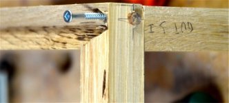
I glued the two sides of the post together with the bolt attached to the rod and crossed my fingers [scared] to hope it would be possible to unscrew the rod once the glue had dried. It was! [big grin] Even better, it was then possible later to screw the rod back into the captured bolt.
The post was then planed down to 6 centimetres on each side (being careful to keep the channel in the middle):
[attachthumb=#11]
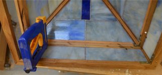
The lamp base plan calls for the exclusive use of oak but, since the shade utilizes both oak and walnut, I decided to use some walnut on the base as well. So the four pole supports are to be walnut. In this photo the pattern for a support is being transferred to a template make use of a sliding bevel and a blending curve (both purchased at Lee Valley):
[attachthumb=#12]
The column support pieces were cut out of this 25 millimetre thick walnut board using a Festool jigsaw equipped with a scrolling blade:
[attachthumb=#13]
Unfortunately, this particular blade snapped when it hit a knot: [huh]
[attachthumb=#14]
That surprised me. I have used this type of blade a lot over the last nine years in two different Festool jigsaws and have seldom known one to break. I carried on with the replacement blade and the results were great in that all four column support pieces were almost exactly the same size. I ganged them together with a couple of clamps and sanded the curve a little bit with 80 grit paper on a Festool linear sander (Duplex) in order to remove the slight differences:
[attachthumb=#15]
The feet are constructed from two oak blocks assembled with a half lap joint. I cut the large dados for the joint using several passes with a “newish” Forrest dado-set on a General 650 table saw:
[attachthumb=#16] [attachthumb=#17] [attachthumb=#18]
I’m quite happy with the joint.
I cut a 19 degree bevel at both ends of both feet, again using my table saw:
[attachthumb=#19]
Next, I needed to cut these marked pieces out of the feet:
[attachthumb=#20]
I decided to use my large bandsaw for the angled cuts and the dado blade set on my table saw for the straight cuts:
[attachthumb=#21] [attachthumb=#22]
The results were acceptable:
[attachthumb=#23]
Last year I made a lamp shade utilizing stained lass, oak, and walnut and gave the shade to my wife, Margaret, for Christmas. I promised to make the base ASAP.
Here is a photo of that lampshade under our tree:
[attachthumb=#1]
The lampshade plan was for a table lamp but I thought that I could easily extend the plan to make a floor lamp base. So, in January, I made a prototype base out of scrap wood but it didn’t seem right. Somehow, the in extending the table lamp base to a floor lamp base then proportions got out of whack; so I set the project aside. As with so many things that I set aside, it was not until many months later that I got back to it. This time I decided to make a base using a floor lamp plan that I found in Wood magazine. (The plan for the shade came from Fine Woodworking.)
[attachthumb=#3]
The rough quarter-sawn white oak that I put into my work shed to acclimatize a year ago:
[attachthumb=#2]
is certainly now well acclimatized. [smile]
Before I get started, I should explain that, by mistake, I left my MFT at Pellow’s Camp [crying] when closing up last September. So, now my MFT is 1,000 kilometres away and some tasks that would have been done utilizing that table and either a track saw or router will have to be done using other tools.
I planed the boards I am using on my new Hammer jointer-planer combo. But, rather than using the jointer to make a square edge, I prefer to use my Festool track saw equipped with a Panther blade for ripping:
[attachthumb=#4] [attachthumb=#5]
Using the same saw, I ripped a the 33 millimetre board that had just been jointed into a couple of pieces approximately 65 millimetres wide. These pieces will later be glued together to form the floor lamp’s column. Once these boards have been glued together, I will trim the column to be 60 millimetres square.
Next, I routed a channel wide enough to hold a 3/8 inch threaded rod in the inside centre of both the column boards:
[attachthumb=#6]
The rod fits well:
[attachthumb=#7]
The short piece of rod that came with the standard lamp kit that I purchased was much too short to provide adequate support, so I had to cut a longer piece from a separately purchased rod:
[attachthumb=#8]
I want the rod to be both adjustable and removable so I embedded a bolt within the channel. In order to do this, my drill press was used to “carve” a slot at right angles to the channel and a little way down in the channel:
[attachthumb=#9] [attachthumb=#10]
I glued the two sides of the post together with the bolt attached to the rod and crossed my fingers [scared] to hope it would be possible to unscrew the rod once the glue had dried. It was! [big grin] Even better, it was then possible later to screw the rod back into the captured bolt.
The post was then planed down to 6 centimetres on each side (being careful to keep the channel in the middle):
[attachthumb=#11]
The lamp base plan calls for the exclusive use of oak but, since the shade utilizes both oak and walnut, I decided to use some walnut on the base as well. So the four pole supports are to be walnut. In this photo the pattern for a support is being transferred to a template make use of a sliding bevel and a blending curve (both purchased at Lee Valley):
[attachthumb=#12]
The column support pieces were cut out of this 25 millimetre thick walnut board using a Festool jigsaw equipped with a scrolling blade:
[attachthumb=#13]
Unfortunately, this particular blade snapped when it hit a knot: [huh]
[attachthumb=#14]
That surprised me. I have used this type of blade a lot over the last nine years in two different Festool jigsaws and have seldom known one to break. I carried on with the replacement blade and the results were great in that all four column support pieces were almost exactly the same size. I ganged them together with a couple of clamps and sanded the curve a little bit with 80 grit paper on a Festool linear sander (Duplex) in order to remove the slight differences:
[attachthumb=#15]
The feet are constructed from two oak blocks assembled with a half lap joint. I cut the large dados for the joint using several passes with a “newish” Forrest dado-set on a General 650 table saw:
[attachthumb=#16] [attachthumb=#17] [attachthumb=#18]
I’m quite happy with the joint.
I cut a 19 degree bevel at both ends of both feet, again using my table saw:
[attachthumb=#19]
Next, I needed to cut these marked pieces out of the feet:
[attachthumb=#20]
I decided to use my large bandsaw for the angled cuts and the dado blade set on my table saw for the straight cuts:
[attachthumb=#21] [attachthumb=#22]
The results were acceptable:
[attachthumb=#23]
")