Rob-GB
Member
- Joined
- Nov 7, 2009
- Messages
- 1,101
When I first heard about this project my creative juices and yearning for a new challenge peaked.
Now I wish I was not so enthusiastic.
I am posting this, not as a Festool made project, although my Festool’s were a huge help in areas of the work ( the MFT3 really came to the fore while on site and made my life so much easier), but as a success clutched, desperately, from the jaws of defeat and incompetence.
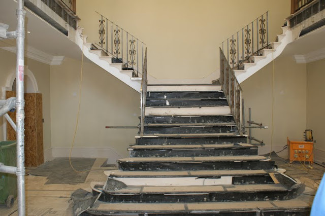
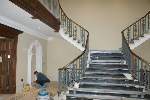
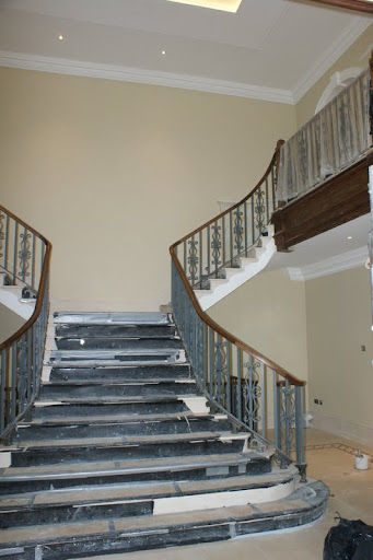
From the architects drawings the main staircase of marble over a cast concrete substrate with bespoke metal balustrade with a steel base rail supported on cast Fleur de Lys and a smaller top (fixing) rail, to which a black walnut handrail would, flowing gracefully upwards to the landing newels, be attached.
Sounds good eh!
Six weeks after we were supposed to start we visited the site to survey/template etc the steel works. They were still not completed.
We returned later......
What had been installed was just plain wrong!

I had a discussion with the site agent and the metal guys and it became apparent that the agent was lost and the steel guys had no clue as to what was expected or how to do it. I tried to explain that the required curves are only circular sections on plan but are, in fact, elliptical in nature, due to the rake of the stair. They are, for example, what you would get if you sliced a pipe at the same angle as the rake.
I knew I was on a lost cause when the main metal guy said “now you’re just being technical”
A further meeting was arranged at which I was told in no uncertain terms that the metalwork already installed could or would not be redone and I would have to work to it. So I set about doing a complete survey of the stair and the scale of the problem became greater with alarming clarity.
The stair is supposed to be mirrored from the centre line of the ground floor to landing fantailed section and split left and right to a windered section to the gallery landing.
It is not.
The rise and going vary and either side do not marry up, neither do the curves on plan or even where the stair meets the first landing and turns left or right.
The stone work is not accurate...big time!
The holes for the steel rods, which are epoxy grouted to the stone/concrete, to which the 50x10mm base rail is welded are at best measured off the stone but with no setting out for the straight runs of handrail being 90° to one another. Thus compounding the inaccuracies.
Add to this that the top fixing rail on the straight runs varied in both height from riser line and in pitch, while the lower curves to the volutes have the look of a scenic railway (a tame roller coaster).


When it came to the part done upper section between gallery landing newel and upper straight section, I’m afraid I lost the plot a bit.....
“ I think I can get over the rest but I am not even going to think about putting my name to that!!!”
It was a few days later that I was on site and the architect pitched up to discuss that point with the metal guys....
MG “well it follows the stair”
Arch “ but it’s wrong!”
MG “it follows the curve though”
Arch “ not quite, and the pitch is wrong, it looks wrong! ...er Rob? Have you got a moment?”
After a discussion, in which I re-iterated my previous point about tubes sliced thru’, it was agreed that I would rough out the handrail and they would get a blacksmith friend shape the metal to suit!
The day I handed over the handrail sections, in the square with groove formed for the fixing rail, I, with witnesses said “don’t let him burn the hell out of them or get them wet, ‘cos that’s the two things they’re prone to do!”
Guess what.
Not only that but the flipping metal did not actually match the groove and a whole half day was spent with me babysitting their attempts to grind, heat, twist and clamp the metal into submission...using my Festool clamps!

When it was finally done I asked them to not alter the shape or plane of the metal when they installed the 25mm square balusters. I should have saved my breath.
Now, I know from experience that metal will tend to twist and warp when welded, that is a given and to be expected....but to raise and bend the top fixing rail plus or minus 15mm from what was a reasonable fit to the handrail beggars belief!


I am not joking when I say that I had panic attacks on the 64 mile drive to the site several times and here’s why.
When the job first came in I was sub-contracting to a guy I class as a friend, he asked me “if we get the job will you stay around and see it through?”
I made a promise to do so, “even if I win the lottery, mate”, because a prestigious project like this is rare these days and I enjoy working with him. On paper it also looked like an achievable challenge. It should have been a win-win project.
Instead I found myself phoning the boss with problem after problem each day, which in itself is a major downer. I am a solution orientated person but each call meant a solution that was going to cost both time and money to him, I felt like a heel, like I was letting him down.
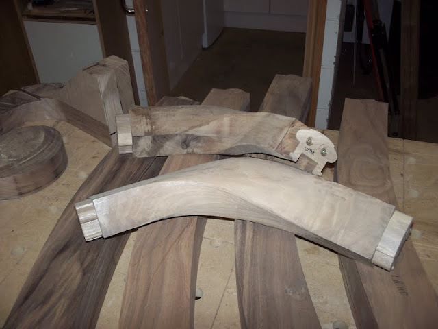
At this point I’d like to show some work in progress pics as you will see the amount of work that goes into it. We start with roughing out volutes and curved sections and form a section of rail that is “square” but curved and twisted to flow up and around the curves of the stair.


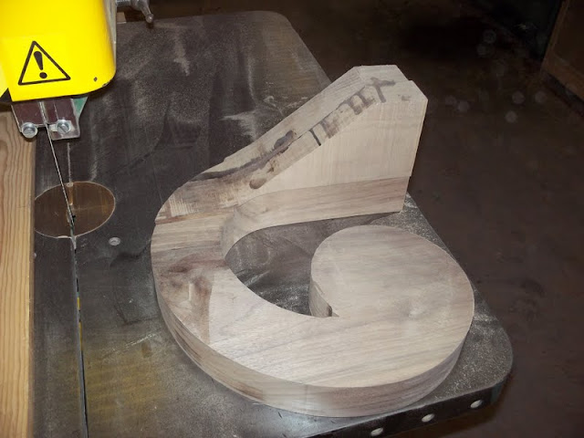
The roughing out is done on the band saw, then cleaned up with spoke shaves to the lines produced from a section I printed out from my CAD drawings.
These drawings are known as “Tangents” and are the means for supplying the required twist in the curve. The curve is of course the plan view of the railing and the tangent geometry will indicate how thick the board needs to be.
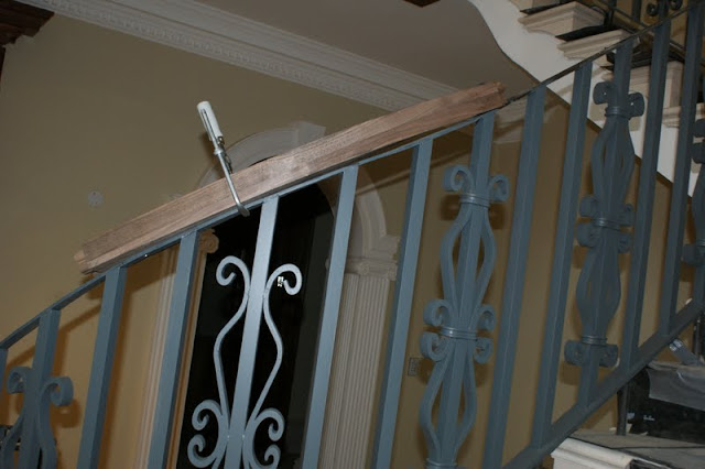
In the pic below you can see the result of a board cut to the curve and the section of straight hand rail screwed to it aligned to the tangent.
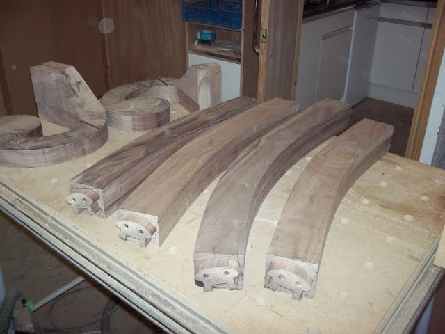
Where the rail has been squared to the tangents to get the twist-


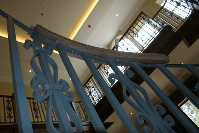
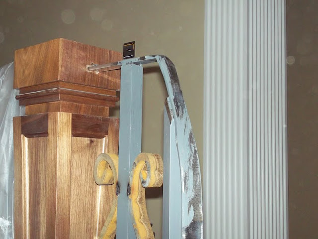
Trial fit before moulding,
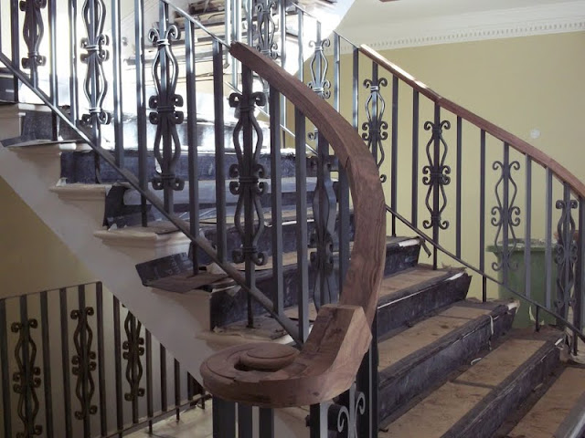

This pic probably demonstrates how hard the job was....


The handrails had to be altered yet again to suit the metal, breaking the glue joints and altering the angle of the sections re-gluing, shaping or changing sections. Some of this was done on site and my MFT3 and its new buddy the leg vice really came to the fore.

I had some cork sanding blocks screwed to the jaws to assist holding the shaped components.
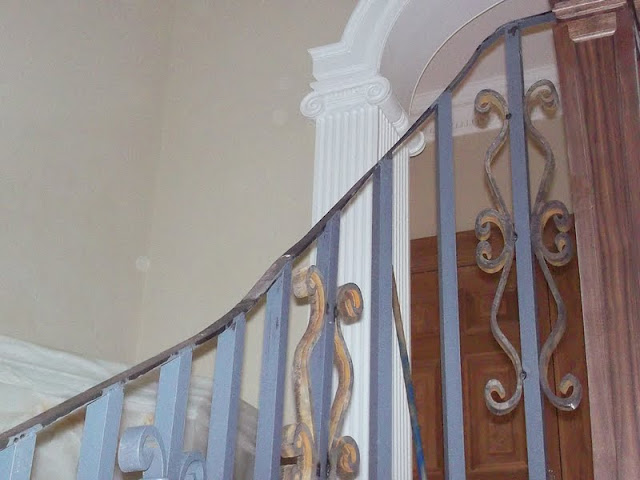
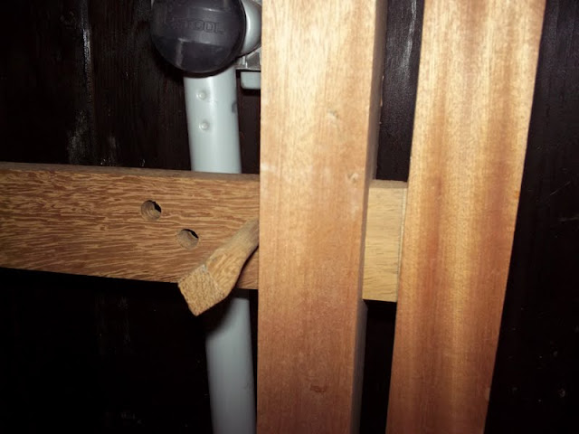
To overcome some of the problems the groove in the underside of the hand railing was made wider than the fixing rail and in places I trenched it deeper, by hand, to accommodate the undulations. Each cover fillet, the wooden piece on the underside that fills the space between balusters and hides the fixing rail had to be individually made to suit in curve, width and thickness in an attempt to make it “look right”.


The end result doesn’t look too bad I suppose but I see every compromise in there.


I have to say that huge thanks go out to 3 guys that worked with me on this project,
Baz: For his sterling work in helping to hand carve/mould some of the curved parts, a much quicker carver than I. He is also a great sounding board to bounce ideas off and nice fella to know.
Young Tom: For his assistance during some of the fitting, for being up at stupid o’clock for the drive up and his humour even when on that seemingly endless sanding routine! A hard worker and cool guy.
“Magic” Johnson: Everyone calls him “Magic”, I think he told me his real name once! Again a top bloke to work with, we did some other installs on this site together and he helped me with the complete survey. Magic has since moved to Australia...a bit extreme but I know how he feels!
Then of course my Boss: Daz, throughout my “consults” (that’s arguments) with the metal guys, project management (an oxymoron if ever!) and sensible architect, he had my back, he listened to what I said and acted on it, he believed in me when I was doubting myself and about to walk away from the job and my promise.........and I never break a promise.
For those that read this far, my sincerest thanks.
I learnt a lot from this project, not just about the craft I love but about myself too.
Rob.
Now I wish I was not so enthusiastic.
I am posting this, not as a Festool made project, although my Festool’s were a huge help in areas of the work ( the MFT3 really came to the fore while on site and made my life so much easier), but as a success clutched, desperately, from the jaws of defeat and incompetence.
From the architects drawings the main staircase of marble over a cast concrete substrate with bespoke metal balustrade with a steel base rail supported on cast Fleur de Lys and a smaller top (fixing) rail, to which a black walnut handrail would, flowing gracefully upwards to the landing newels, be attached.
Sounds good eh!
Six weeks after we were supposed to start we visited the site to survey/template etc the steel works. They were still not completed.
We returned later......
What had been installed was just plain wrong!
I had a discussion with the site agent and the metal guys and it became apparent that the agent was lost and the steel guys had no clue as to what was expected or how to do it. I tried to explain that the required curves are only circular sections on plan but are, in fact, elliptical in nature, due to the rake of the stair. They are, for example, what you would get if you sliced a pipe at the same angle as the rake.
I knew I was on a lost cause when the main metal guy said “now you’re just being technical”
A further meeting was arranged at which I was told in no uncertain terms that the metalwork already installed could or would not be redone and I would have to work to it. So I set about doing a complete survey of the stair and the scale of the problem became greater with alarming clarity.
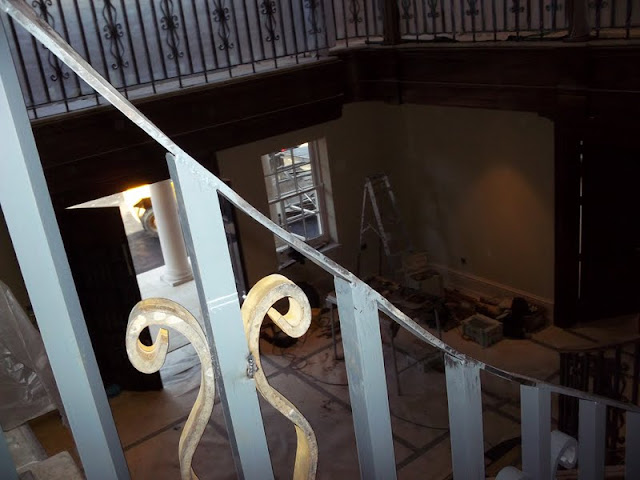
The stair is supposed to be mirrored from the centre line of the ground floor to landing fantailed section and split left and right to a windered section to the gallery landing.
It is not.
The rise and going vary and either side do not marry up, neither do the curves on plan or even where the stair meets the first landing and turns left or right.
The stone work is not accurate...big time!
The holes for the steel rods, which are epoxy grouted to the stone/concrete, to which the 50x10mm base rail is welded are at best measured off the stone but with no setting out for the straight runs of handrail being 90° to one another. Thus compounding the inaccuracies.
Add to this that the top fixing rail on the straight runs varied in both height from riser line and in pitch, while the lower curves to the volutes have the look of a scenic railway (a tame roller coaster).
When it came to the part done upper section between gallery landing newel and upper straight section, I’m afraid I lost the plot a bit.....
“ I think I can get over the rest but I am not even going to think about putting my name to that!!!”
It was a few days later that I was on site and the architect pitched up to discuss that point with the metal guys....
MG “well it follows the stair”
Arch “ but it’s wrong!”
MG “it follows the curve though”
Arch “ not quite, and the pitch is wrong, it looks wrong! ...er Rob? Have you got a moment?”
After a discussion, in which I re-iterated my previous point about tubes sliced thru’, it was agreed that I would rough out the handrail and they would get a blacksmith friend shape the metal to suit!
The day I handed over the handrail sections, in the square with groove formed for the fixing rail, I, with witnesses said “don’t let him burn the hell out of them or get them wet, ‘cos that’s the two things they’re prone to do!”
Guess what.
Not only that but the flipping metal did not actually match the groove and a whole half day was spent with me babysitting their attempts to grind, heat, twist and clamp the metal into submission...using my Festool clamps!
When it was finally done I asked them to not alter the shape or plane of the metal when they installed the 25mm square balusters. I should have saved my breath.
Now, I know from experience that metal will tend to twist and warp when welded, that is a given and to be expected....but to raise and bend the top fixing rail plus or minus 15mm from what was a reasonable fit to the handrail beggars belief!
I am not joking when I say that I had panic attacks on the 64 mile drive to the site several times and here’s why.
When the job first came in I was sub-contracting to a guy I class as a friend, he asked me “if we get the job will you stay around and see it through?”
I made a promise to do so, “even if I win the lottery, mate”, because a prestigious project like this is rare these days and I enjoy working with him. On paper it also looked like an achievable challenge. It should have been a win-win project.
Instead I found myself phoning the boss with problem after problem each day, which in itself is a major downer. I am a solution orientated person but each call meant a solution that was going to cost both time and money to him, I felt like a heel, like I was letting him down.
At this point I’d like to show some work in progress pics as you will see the amount of work that goes into it. We start with roughing out volutes and curved sections and form a section of rail that is “square” but curved and twisted to flow up and around the curves of the stair.
The roughing out is done on the band saw, then cleaned up with spoke shaves to the lines produced from a section I printed out from my CAD drawings.
These drawings are known as “Tangents” and are the means for supplying the required twist in the curve. The curve is of course the plan view of the railing and the tangent geometry will indicate how thick the board needs to be.
In the pic below you can see the result of a board cut to the curve and the section of straight hand rail screwed to it aligned to the tangent.
Where the rail has been squared to the tangents to get the twist-
Trial fit before moulding,
This pic probably demonstrates how hard the job was....
The handrails had to be altered yet again to suit the metal, breaking the glue joints and altering the angle of the sections re-gluing, shaping or changing sections. Some of this was done on site and my MFT3 and its new buddy the leg vice really came to the fore.
I had some cork sanding blocks screwed to the jaws to assist holding the shaped components.
To overcome some of the problems the groove in the underside of the hand railing was made wider than the fixing rail and in places I trenched it deeper, by hand, to accommodate the undulations. Each cover fillet, the wooden piece on the underside that fills the space between balusters and hides the fixing rail had to be individually made to suit in curve, width and thickness in an attempt to make it “look right”.
The end result doesn’t look too bad I suppose but I see every compromise in there.
I have to say that huge thanks go out to 3 guys that worked with me on this project,
Baz: For his sterling work in helping to hand carve/mould some of the curved parts, a much quicker carver than I. He is also a great sounding board to bounce ideas off and nice fella to know.
Young Tom: For his assistance during some of the fitting, for being up at stupid o’clock for the drive up and his humour even when on that seemingly endless sanding routine! A hard worker and cool guy.
“Magic” Johnson: Everyone calls him “Magic”, I think he told me his real name once! Again a top bloke to work with, we did some other installs on this site together and he helped me with the complete survey. Magic has since moved to Australia...a bit extreme but I know how he feels!
Then of course my Boss: Daz, throughout my “consults” (that’s arguments) with the metal guys, project management (an oxymoron if ever!) and sensible architect, he had my back, he listened to what I said and acted on it, he believed in me when I was doubting myself and about to walk away from the job and my promise.........and I never break a promise.
For those that read this far, my sincerest thanks.
I learnt a lot from this project, not just about the craft I love but about myself too.
Rob.