Bohdan
Member
After seeing the Schmitt 32 System videos I started thinking that it was possible to do the same with the LR32 kit.
After several attempts I finally came up with a working version and I will describe how it was made. Most of the dimensions are not critical and you can alter them to suit your requirements.
The steps that I describe are the ones that resulted in my finished jig. My jig is designed to be used on an extended (8' x 2') MFT top and unfortunately due to the length of the LR32 rail will not fit on an MFT. Mine uses 'headless' dogs to fit my top but if you drill suitable 8mm holes in a piece of ply you can bolt the jig to it and it will work fine.
All of the drilling is done with the LR32 kit and an 8mm bit (the most expensive part of this jig and only available from Festool).
You need a piece of 19mm material about 300mm wide and at least 300mm longer that the widest panel that you will want to drill. You need this width to be able to clamp the rail on the board while drilling.
Mine was 950mm long.
With the LR32 rail set on the 32mm stop drill a row of holes starting 224mm from one end and 80mm from the edge.
Flip the rail and repeat the drilling on the other edge.
Set the width to 96mm and repeat the drilling only on the second edge.
Flip the rail and on the first edge with the setting on 64mm repeat the drilling.
Now change the stop on the rail to 16mm and the width to 87.8mm and drill the mounting holes. Mine were at 48mm and 528mm to suit my extended MTF top.
The 87.8mm dimension is fixed by the difference in the 96mm hole spacing of the MFT and the position of the 8mm holes in the ends of the LR32 rail. I used 8mm bolts with the thread cut off and the end rounded over as a locating pin to move the rail up and down the jig.
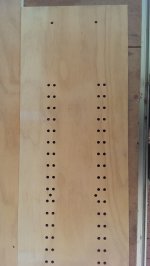
You should now have a board that looks like this.
View attachment 1
Cut thru the centre of the board so that you get two pieces 110mm wide.
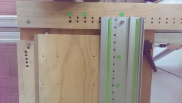
I then drilled and tapped an 8mm threaded hole into the edge of the board for an adjustable stop. Mounted the boards on the MFT top using the LR32 rail to space the two ends apart.
The stops need to be adjusted so that the first hole is 32mm from the top of a panel and this adjustment also compensates for the router not being exactly central. If the router is removed from the LR32 jig then when you reinstate it you plunge the (stationary) drill into a piece with a correctly drilled hole and tighten the clamps on the router.
View attachment 2
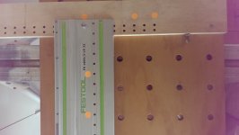
This shows the jig in use. The stop at the bottom with the row of holes at an angle is for all the common setups.
The hole with the screw in it is the 37mm from the front setting drilled at 21mm.
Correction :-I have since found that the hole measurements and subsequent drilling for the remaining holes was taken from a different edge and was therefore incorrect. They are to be taken as down from the front edge of the stop and should be the corrected values
The next one sets the drawer rail 1/2 mm above the bottom of the drawer drilled at26.5 35.0mm.
The remaining holes are for the hinge locations at 3, 4, 5, 6 and 7mm from the edge of the door drilled at37.5, 36.5, 35.5, 34.5 and 33.5 41.5, 40.5, 39.5, 38.5, 37.5, 35.5mm.
You use the other set of holes that were drilled on the 16mm setting to use a cruciform hinge. If you only use parallel hinges you don't need the 16mm set of holes.
The 0.1mm settings are easy to achieve as the scale on the LR32 width stops is a (hard to see) vernier but in bright sunlight I was able to use it.
I didn't have a piece the right length when I made the stop so I move the stop to the other end when doing the other sides. I will be making a stop that is the right length as moving it is proving to be a PITA.
I use the green dots to mark which holes to drill and on the other side I use orange.
View attachment 3
Sorry for such a drawn out post with such lousy pics but these days I only have my phone camera.
The main advantage of the jig is that once you have settled on and marked where the holes are going the panel literally takes seconds to drill and you can put it away and the next one (if its the same) requires no setting up.
If any thing is uncertain ask away and I will try to explain the mystery.
After several attempts I finally came up with a working version and I will describe how it was made. Most of the dimensions are not critical and you can alter them to suit your requirements.
The steps that I describe are the ones that resulted in my finished jig. My jig is designed to be used on an extended (8' x 2') MFT top and unfortunately due to the length of the LR32 rail will not fit on an MFT. Mine uses 'headless' dogs to fit my top but if you drill suitable 8mm holes in a piece of ply you can bolt the jig to it and it will work fine.
All of the drilling is done with the LR32 kit and an 8mm bit (the most expensive part of this jig and only available from Festool).
You need a piece of 19mm material about 300mm wide and at least 300mm longer that the widest panel that you will want to drill. You need this width to be able to clamp the rail on the board while drilling.
Mine was 950mm long.
With the LR32 rail set on the 32mm stop drill a row of holes starting 224mm from one end and 80mm from the edge.
Flip the rail and repeat the drilling on the other edge.
Set the width to 96mm and repeat the drilling only on the second edge.
Flip the rail and on the first edge with the setting on 64mm repeat the drilling.
Now change the stop on the rail to 16mm and the width to 87.8mm and drill the mounting holes. Mine were at 48mm and 528mm to suit my extended MTF top.
The 87.8mm dimension is fixed by the difference in the 96mm hole spacing of the MFT and the position of the 8mm holes in the ends of the LR32 rail. I used 8mm bolts with the thread cut off and the end rounded over as a locating pin to move the rail up and down the jig.
You should now have a board that looks like this.
View attachment 1
Cut thru the centre of the board so that you get two pieces 110mm wide.
I then drilled and tapped an 8mm threaded hole into the edge of the board for an adjustable stop. Mounted the boards on the MFT top using the LR32 rail to space the two ends apart.
The stops need to be adjusted so that the first hole is 32mm from the top of a panel and this adjustment also compensates for the router not being exactly central. If the router is removed from the LR32 jig then when you reinstate it you plunge the (stationary) drill into a piece with a correctly drilled hole and tighten the clamps on the router.
View attachment 2
This shows the jig in use. The stop at the bottom with the row of holes at an angle is for all the common setups.
The hole with the screw in it is the 37mm from the front setting drilled at 21mm.
Correction :-I have since found that the hole measurements and subsequent drilling for the remaining holes was taken from a different edge and was therefore incorrect. They are to be taken as down from the front edge of the stop and should be the corrected values
The next one sets the drawer rail 1/2 mm above the bottom of the drawer drilled at
The remaining holes are for the hinge locations at 3, 4, 5, 6 and 7mm from the edge of the door drilled at
You use the other set of holes that were drilled on the 16mm setting to use a cruciform hinge. If you only use parallel hinges you don't need the 16mm set of holes.
The 0.1mm settings are easy to achieve as the scale on the LR32 width stops is a (hard to see) vernier but in bright sunlight I was able to use it.
I didn't have a piece the right length when I made the stop so I move the stop to the other end when doing the other sides. I will be making a stop that is the right length as moving it is proving to be a PITA.
I use the green dots to mark which holes to drill and on the other side I use orange.
View attachment 3
Sorry for such a drawn out post with such lousy pics but these days I only have my phone camera.
The main advantage of the jig is that once you have settled on and marked where the holes are going the panel literally takes seconds to drill and you can put it away and the next one (if its the same) requires no setting up.
If any thing is uncertain ask away and I will try to explain the mystery.