Medium BF/MFT Workbench Build

Looks awesome Mike! What a bench!  [big grin]

MikeGE said:
In the 100mm high drawer above the sander, I have the bench dogs.

Item24-55-L.jpg

^^I really need to do something like this for small bits.
 
MikeGE said:
The bottom of the SE1 begged for modification, so I threaded the four holes in the corner for M10.

Item24-58-M.jpg

Mike, it looks like you threaded the (4) spots on the bottom that don't go through the base, is that correct? 

I just got my VAC SYS Set from the Festool Recon site and looking to make a similar mount for the 2 heads.  Also ordered some hose and fittings to clean up the lines with quick disconnects similar to your setup.

Also, how thick is the Kaizan foam you used for your drawers?
 
08G8V8 said:
Mike, it looks like you threaded the (4) spots on the bottom that don't go through the base, is that correct? 

I just got my VAC SYS Set from the Festool Recon site and looking to make a similar mount for the 2 heads.  Also ordered some hose and fittings to clean up the lines with quick disconnects similar to your setup.

Also, how thick is the Kaizan foam you used for your drawers?

Yes, I threaded the four spots that don't go through the base with a set of M10x1.5 taps.  I drilled them first with the 8.5mm drill to make sure they were the correct diameter for the tap.  I might have been able to tap them without drilling, but since I had the drill with the taps, I made sure.

I started with the taper tap, then the plug tap, followed by the bottoming tap.  McMaster-Carr sells these taps as a set.

The Kaizen foam for all of the drawers is 30mm and is the thinnest foam I had on hand.  The foam in the Woodpeckers drawers are solid black, but the foam in the TSO drawer has the white center.  I used this since it makes it easier to find the small hex keys, as well as tell when a small part is missing.

One thing I forgot to do before I cut the hoses on my VAC SYS was to check how long it takes for the vacuum to leak down after the pump is turned off.  I can't remember if the SE1 held a vacuum for a long time, but now it leaks down to the point where it won't hold a small board in the vertical position for more than ten seconds after the pump is turned off.  This is not an issue when the pump is operating, as it pulls the same vacuum as before, but I was curious.  If you think about it, would you check this before you cut your lines and put the new connectors on and post the time here?
 
Thanks for the info.  I just placed an order with McMaster yesterday for some of the fittings.  I went with the quick connect someone posted in the Vacsys hose threads from Lowes. I will look into tapping these holes.  I will see how these cheaper fittings work and change to the European style quick connects from McMaster if needed.

I bought a couple sheets of 20mm foam from Fastcap awhile back, but think a thicker foam would be better, so I will look at the 30mm and 57mm they sell. They raised the price considerably, but if you buy a kit of 8 sheets of 30mm or 5 sheets of 57mm the price is reasonable per sheet.

I will do some tests after I get my units mounted, and then with the modified lines and report back.

Sent from my iPad using Tapatalk
 
08G8V8 said:
Thanks for the info.  I just placed an order with McMaster yesterday for some of the fittings.  I went with the quick connect someone posted in the Vacsys hose threads from Lowes. I will look into tapping these holes.  I will see how these cheaper fittings work and change to the European style quick connects from McMaster if needed.

I bought a couple sheets of 20mm foam from Fastcap awhile back, but think a thicker foam would be better, so I will look at the 30mm and 57mm they sell. They raised the price considerably, but if you buy a kit of 8 sheets of 30mm or 5 sheets of 57mm the price is reasonable per sheet.

I will do some tests after I get my units mounted, and then with the modified lines and report back.

Sent from my iPad using Tapatalk

I used the European fittings from PCL because...well, I live in Europe.  [big grin]  I'd buy fittings to match the hoses and equipment for your area.  I had a few air nailers that I bought from Harbor Freight and brought with me.  I had to change the fittings on the nailers because they wouldn't mate with the European hose fittings.  Fortunately, they use the same pipe thread dimensions here for water and air lines.

If I had some 20mm Kaizen, I would have used it.  I think it would have worked fine for the Woodpeckers and TSO drawers in my workbench.  Other than the angle clamps, I didn't need to remove more than a few layers of the Kaizen to lock in the tools.
 
I bought the threaded fittings from McMaster in order to get the BSPP threads to match the Festool fittings, as I doubt I can source those locally. I bought 1 of the sets from Lowes and it attaches to the Festool male plugs and the plug dimensions on the Festool plugs match the plug dimensions that come in the Lowes kit.  Will see how it works before I have to shell out the $$ for the European style quick connects.

Sent from my iPad using Tapatalk
 
I used the European fittings from PCL because...well, I live in Europe.  [big grin] 

well well, it looks like your beloved wife must be very proud of you - not just because of your obvious striving and degree of perfection, but also your very tidyness compared to the average diy guy when looking at your posted images.

so, lucky lucky german wife she is, in particular when i think of all the wonderful nice christmas gifts you are able to create for her now... 8)

in terms of your project a couple of more questions have come to mind:

- who and what is pcl as i don´t know anything about it so far?
- how would you describe valchromate, its properties and your experience so far in comparison to mdf?
- bench dogs: i have noticed that you seem to use 2 different benchdog systems: the one from benchdogs, and the other one from ujk. what´s the reason for this?
- and the last one for today: in hindsight what would you differently with your workbench project ? in terms of eg. design/ construction of the bench, work order, parts being used, work flow etc.
 
BeGood said:
I used the European fittings from PCL because...well, I live in Europe.  [big grin] 

well well, it looks like your beloved wife must be very proud of you - not just because of your obvious striving and degree of perfection, but also your very tidyness compared to the average diy guy when looking at your posted images.

so, lucky lucky german wife she is, in particular when i think of all the wonderful nice christmas gifts you are able to create for her now... 8)

in terms of your project a couple of more questions have come to mind:

- who and what is pcl as i don´t know anything about it so far?
- how would you describe valchromate, its properties and your experience so far in comparison to mdf?
- bench dogs: i have noticed that you seem to use 2 different benchdog systems: the one from benchdogs, and the other one from ujk. what´s the reason for this?
- and the last one for today: in hindsight what would you differently with your workbench project ? in terms of eg. design/ construction of the bench, work order, parts being used, work flow etc.

Thank you!  The cleanliness is a byproduct of a my military experience.  Every tool cleaned and stored when not needed, and the work area cleared.  This is now second nature.

1.  What is PCL?  Pneumatic Components Ltd. is a UK company that specializes in air lines and air line fittings.  It is one of many sources, but one that [member=2839]scholar[/member] recommended. 

2.  Valchromat.  This is a product originally from Portugal (I think), and it similar to moisture resistant MDF.  However, it is a lot easier to work with than MDF, machines well (except for the blowouts from the 20mm cutter), and is easy on cutting edges.  It is more expensive than MDF and can only be purchased in full sheets here, but is available in about a dozen colors.  If I want MDF, I can buy cut to order pieces from the local hardware store, but the thickest MDF stocked is 18mm.  I cannot buy MRMDF, but can special order it wiht a four-week lead time.  After working with Valchromat, I won't consider using anything else for a workbench top.

3.  Benchdogs.  I bought the UJK bench dogs during one of the sales at Axminster in the UK.  I bought the Bench Dogs version for the fence because they were the only version I could find that had slots that would accept the hardware for the fence T-track.

4.  What would I do differently?  I would think out the design a bit more before ordering the aluminum extrusion and add the extra horizontal support pieces and drawer pulls to the original design.  This would have saved me over €300 in extra shipping and the drill jig since the holes would be part of the CNC design.  I might consider making the workbench 2.5 meters long instead of 2 meters, but I'll have to use my workbench for a while to see if I have any "I wish I had that extra half meter" moments.  This would give me an additional tool or drawer storage bay on each side.  However, this would also add more weight to the workbench...and it is a beast now.  I would also consider use the lighter version of the extrusion for all of the 40x40mm sections except for the two 2-meter sections at the bottom.  I don't think there is anything to be gained by using the solid version when flexing is not an issue.  Otherwise, I am very happy with the workbench as is.
 
from your project also including your pics and what you´ve written so far i believe many of us here can learn quite a bit from you and your expertise - eg. how you approach a quite complex project, but also in terms of your military discipline and which helps a lot in the daily work:

when you stick to tidiness and made it a strict rule to follow on a daily base i suppose you always know where things are during a project. as such it makes you waste less time, energy and frustration in terms of this very well known searching, searching and searching for tools etc. ;)

in terms of your mentioned christmas wish of having just this extra half meter may i suggest a simple idea and which hopefully also plays into your strategic mind set:

why not add a tool tray, maybe a routed box to the far end of your workbench and where you´ve got the 2 sockets - a flexible box that you simply can click on to your extrusion rail whilst making use of the t-slot and which you can take off at any time...

the additional benefit might be that you would have a proper excuse in the run up for christmas - i mean in case you´ve run out of ideas (or time) in terms of making christmas presents for your beloved wife and that show your ongoing strong affection for her (and not just for the workbench)...

by the way, what do you think of making a tasteful lovely little wooden box maybe also including decorative brass inlays and made of exotic wooden material (and maybe even incensed with an irresistible fragrance to the taste of your wife) and which has enclosed this teeny weeny sparkling $1,000,000 diamond bracelet or ring or necklace or... and which is, well, every girls´ best friend? well, if i remember correctly...

anyway, as a mentioned just an idea [smile]

 
MikeGE said:
08G8V8 said:
Mike, it looks like you threaded the (4) spots on the bottom that don't go through the base, is that correct? 

I just got my VAC SYS Set from the Festool Recon site and looking to make a similar mount for the 2 heads.  Also ordered some hose and fittings to clean up the lines with quick disconnects similar to your setup.

Also, how thick is the Kaizan foam you used for your drawers?

One thing I forgot to do before I cut the hoses on my VAC SYS was to check how long it takes for the vacuum to leak down after the pump is turned off.  I can't remember if the SE1 held a vacuum for a long time, but now it leaks down to the point where it won't hold a small board in the vertical position for more than ten seconds after the pump is turned off.  This is not an issue when the pump is operating, as it pulls the same vacuum as before, but I was curious.  If you think about it, would you check this before you cut your lines and put the new connectors on and post the time here?

I haven’t changed my lines over yet, but I just tested the holding time of a 22”x10” piece of 3/4” plywood, in the vertical position with the largest diameter pod that comes with the SE1 and it held for about 5 minutes before it loses hold.  I tested 2 times and both were around 5 minutes.

Much longer than your 10 seconds. I guess I will see what I get when I swap the lines.

Sent from my iPad using Tapatalk
 
Hi Mike,

your workbench is really awesome. Thanks for sharing and a special thanks for the detailed explanations and photos.

I'm also thinking about building a MFT style workbench with ITEM profiles. One thing, that is causing a severe headache, is the milling of the profile slots. No way I can manage it in such a clean way as you did.

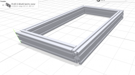
Therefore I was thinking about an alternative way, that does not require any milling and came up with this idea: Why not mount the top frame in an asymmetric way as in the following sketch:

View attachment 1

All slots would be accessible without any milling.

I found a lot of great workbench builds, where the creator milled the slots of the profile. I did not find a single example with an asymmetric top frame as show above.

Now my main question is: Am I the first one with this idea or does this "asymmetric" design have any major disadvantages?

Thanks a lot for you opinions.

Best regards from Switzerland...
 

Attachments

  • item_top_frame.PNG
    item_top_frame.PNG
    199.7 KB · Views: 318
sb11 said:
Hi Mike,

your workbench is really awesome. Thanks for sharing and a special thanks for the detailed explanations and photos.

I'm also thinking about building a MFT style workbench with ITEM profiles. One thing, that is causing a severe headache, is the milling of the profile slots. No way I can manage it in such a clean way as you did.

Therefore I was thinking about an alternative way, that does not require any milling and came up with this idea: Why not mount the top frame in an asymmetric way as in the following sketch:

View attachment 1

All slots would be accessible without any milling.

I found a lot of great workbench builds, where the creator milled the slots of the profile. I did not find a single example with an asymmetric top frame as show above.

Now my main question is: Am I the first one with this idea or does this "asymmetric" design have any major disadvantages?

Thanks a lot for you opinions.

Best regards from Switzerland...

Thank you @sb11 and welcome to the FOG! I'm glad you were able to work with the drawings and files.

I had considered the solution you suggested for the top and bottom rails, but decided against it for two reasons.

The first reason is I wanted the long upper and lower rails to carry all of the vertical loads in compression mode. While I was confident item24 would machine the corner joints correctly, I did not want to rely on the corner joint bolt torque alone to carry the loads in shear mode.

The second reason is this would have saved milling only 6 of the 22 slots I wanted. I would still have 16 slots in the 10 vertical rails and 2 other horizontal rails. The channel nuts that hold the VAC SYS SE1 to the table, as well as the Dashboard rail brackets, are permanently mounted to the long upper rails. Having only one entry point on the long rails for clamps would not allow me to use the rest of the rail. As it is now, I have full use of the upper and lower rails for clamps, but have lost the use of the lower half of one vertical rail because of the VAC SYS SE1 channel nut, but I can live with this.

I was a bit apprehensive about using my OF1010 and a carbide cutter to mill the slots in the aluminum extrusion, but I took my time with multiple passes and it worked out very well. The template made the setup and milling much easier than I thought it would be.

If you are not interested in using the vertical rails for clamps, then the asymmetric layout you suggested and no milling should work well.
Best regards from Germany :)
 
Last edited:
Hi Mike,

thanks for the quick reply.

Even though I did not understand all of you explanation (compression mode? shear mode?  ???), I think I got your point.

I think I need to make a detailed sketch first, in order to see, what make sense and what not.

Best regards...
 
sb11 said:
Hi Mike,

your workbench is really awesome. Thanks for sharing and a special thanks for the detailed explanations and photos.

I'm also thinking about building a MFT style workbench with ITEM profiles. One thing, that is causing a severe headache, is the milling of the profile slots. No way I can manage it in such a clean way as you did.

Therefore I was thinking about an alternative way, that does not require any milling and came up with this idea: Why not mount the top frame in an asymmetric way as in the following sketch:

View attachment 1

All slots would be accessible without any milling.

I found a lot of great workbench builds, where the creator milled the slots of the profile. I did not find a single example with an asymmetric top frame as show above.

Now my main question is: Am I the first one with this idea or does this "asymmetric" design have any major disadvantages?

Thanks a lot for you opinions.

Best regards from Switzerland...

[member=77338]sb11[/member] I'd recommend you reconsider milling the slots if that's the only reason you want to offset the corner joints. Milling only requires a router with a 1/4"/6mm bit and literally takes minutes once you jig up the cut. You'll be surprised how easy it is. In another thread I showed a setup that used a 30mm copy ring and didn't required a precise template. If that's of interest I'll find it and link the thread.

Just my [2cents] but the milled slots open up a lot more flexibility using t-slot extrusions.

Also, [welcome]

RMW
 
@sb11, to add to what @richard/RMW wrote, adding the keyhole slots for clamps and other brackets expands the utility of the workbench. It is much easier to add them before you assemble the frame.

If it helps, I still have the router template I made for my workbench. You are welcome to it if you decide to mill the slots, but you will have to add your own cleat on the back of it for the rail alignment. Any straight piece of scrap will work and I think I used a piece of 15mm plywood. I don't have any more of the 8mm channel nuts or screws, but these are readily available from item24 (or any extrusion vendor) if you buy the rails from them. I don't think it would be expensive to ship the piece of plywood from Germany to Switzerland, but it would certainly save you some time.

i-xppb7K8-M.jpg


i-4Sjc3SS-S.jpg


I bought two of the 8mm cutters just in case one broke (it didn't), so I'll include the unused cutter as well. My template was designed to be used with the OF 1010 router and 484176 13.8mm copy ring.
 
Last edited:
Richard/RMW said:
[member=77338]sb11[/member] I'd recommend you reconsider milling the slots if that's the only reason you want to offset the corner joints.

Hi Richard,

thanks for your reply. But what is the reason, you recommend against that? Are there any major disadvantages, when the corner joints are "asymmetric"?

Cheers...
 
MikeGE said:
[member=77338]sb11[/member], to add to what [member=8712]Richard/RMW[/member] wrote, adding the keyhole slots for clamps and other brackets expands the utility of the workbench.  It is much easier to add them before you assemble the frame.

If it helps, I still have the router template I made for my workbench.  You are welcome to it if you decide to mill the slots, but you will have to add your own cleat on the back of it for the rail alignment.  Any straight piece of scrap will work and I think I used a piece of 15mm plywood.  I don't have any more of the 8mm channel nuts or screws, but these are readily available from item24 (or any extrusion vendor) if you buy the rails from them.  I don't think it would be expensive to ship the piece of plywood from Germany to Switzerland, but it would certainly save you some time.

I bought two of the 8mm cutters just in case one broke (it didn't), so I'll include the unused cutter as well.  My template was designed to be used with the OF 1010 router and 484176 13.8mm copy ring.

Hi Mike,

thanks for the offer - really appreciate it. However shipping to Switzerland is quite expensive.

First I have to make up my mind, if I really want to mill the slots or if I find an alternative design, that doesn't require any milling.

Cheers...
 
Hey Mike,

i know this is a old thread, but have a question about de profile.

why do you use 4080 for the bench and 3060 for the fence?
is this for clamps or t-nut size?

greetings John
(from next to .. Belgium)
 
john71 said:
Hey Mike,

i know this is a old thread, but have a question about de profile.

why do you use 4080 for the bench and 3060 for the fence?
is this for clamps or t-nut size?

greetings John
(from next to .. Belgium)

Hi John,

I used 4040 and 4080 extrusion for the structural strength and M8 hardware, but I think I could have used the lighter version of these extrusions without sacrificing any strength.  I never bothered to calculate the total difference in weight between the two versions, but I suspect the difference will be minor compared to the total weight of the workbench with the wood and tools.  I can easily move the workbench around the floor as required and rarely lock more than any two of the four lockable wheels to keep it from moving.

I used the 3060 extrusion for the fence because it didn't need to be structural, I could use M6 hardware for the flip stops and dogs, and I could safely cut away a large portion of the 60mm width to leave a portion still attached to fit under the guide rail.  If I tried to use a piece of the 4080 for the fence, the portion under the guide rail would be about 15mm thick.

I still haven't fabricated any flip stops or stop blocks.  Instead, I've been using the TSO guide rails or stop blocks attached to the Valchromat top for repeat cuts. Eventually, I will make or buy flip stops.  I bought a flip stop from Bench Dogs, thinking it would work, but it is made for 25mm wide profile and doesn't quite fit.

If you are ever in the Darmstadt area, let me know.
 
Hi Mike,

this is an impressive build and a good example of German exquisite craftsmanship. In my basement the most versatile tool is my own designed and built cnc-machine. I used to have enough space there for a partially mobile work table. Now the space is no longer there and also handling the German standard plate sizes is much easier outdoors, since I have to cut them into bite-sized pieces first anyway. Of course, that's easier on the large MFT folding version that has found a home on my garage wall.
Do you buy your wood from Beka in Heppenheim? I lived in Rüsselsheim for many years during my school days and still have some friends there.

Best regards from Breisgau. Soon a bus from Darmstadt will come to the soccer stadium in Freiburg again. Congratulations on the promotion to the first league…

Pierre
 
Back
Top