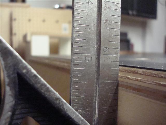
I built an MFT that's been working out great around the shop for some time now. It's on the smaller size (30x48) and haven't needed anything bigger for projects since I built it. Today, on the other hand, was a different story. I wanted to assemble a 72 x 38-inch extrusion frame that will eventually support an assembly table - I get it's ironic that I'd need an assembly table to assemble my assembly table. In the process of figuring out how I'd make it work I pulled out my Dewalt saw horses. I noticed that with the miter saw supports it was just under 3-inches shorter than my MFT.
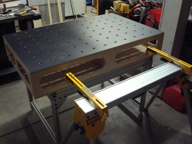
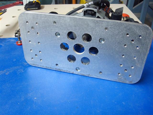
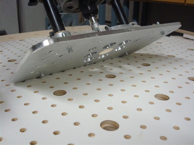
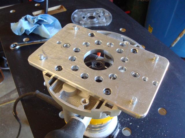
My initial thought was a pair of 2x4's trimmed to the right height and a piece of ply for a work surface. One of my character flaws is I can turn any 15 minute project into an all day project. I found out I didn't have even 6-inches of a 2x4 so I started fiddlin' around and when I was done, I had essentially built another MFT. The oblong slots in the box allow me to put my hand through and squeeze the release levers so I can remove it from the saw horse. The holes were machined using my router base and peg-board trick.
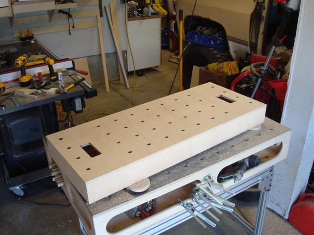
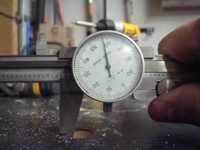
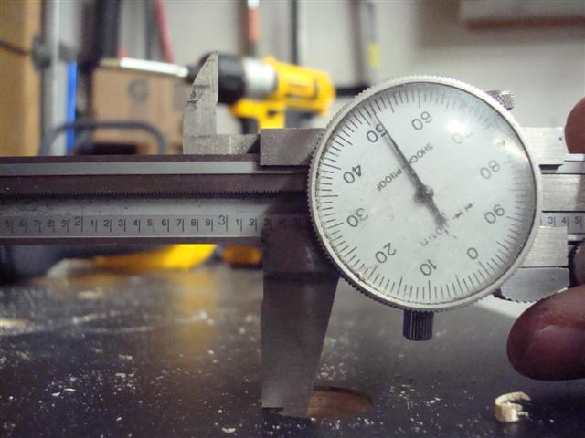
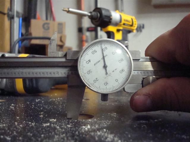
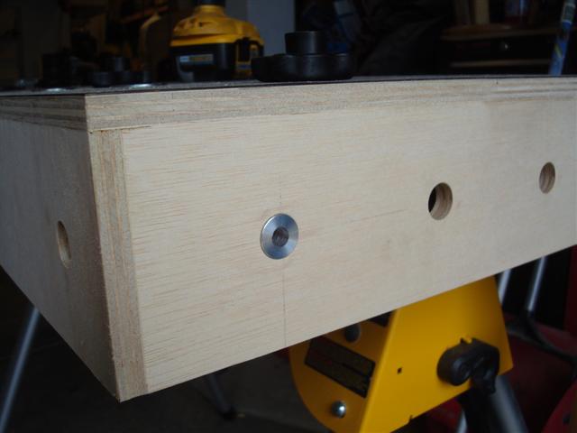
I also drilled the sides and ends so I could clamp on all surfaces. I built up the base with some scrap to get the exact height (though a washer ended up being the final touch to get the exact height).
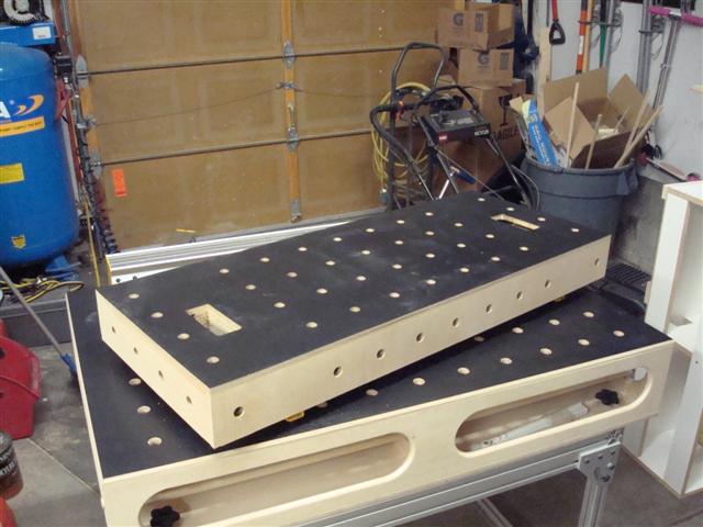
And laminated the surface like the rest of the MFT's.
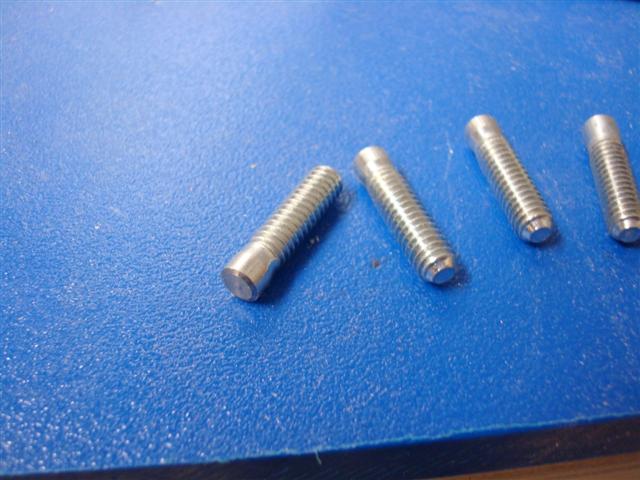
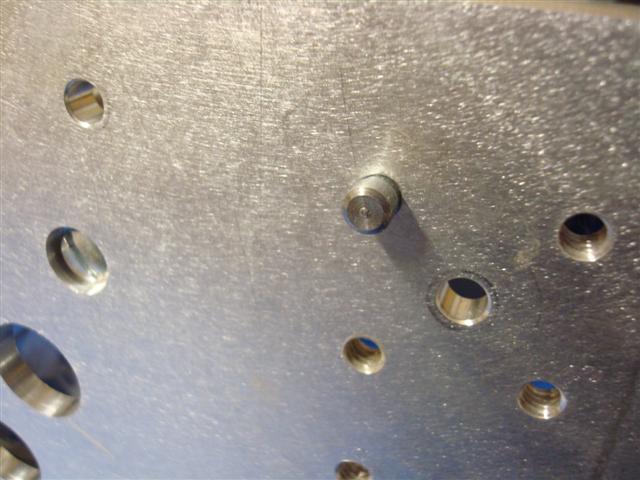
Then while I was about to assemble the other top I had an idea. I made some bushings out of aluminum that fit my 3/4-inch holes.
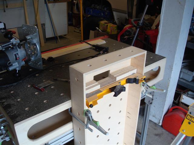
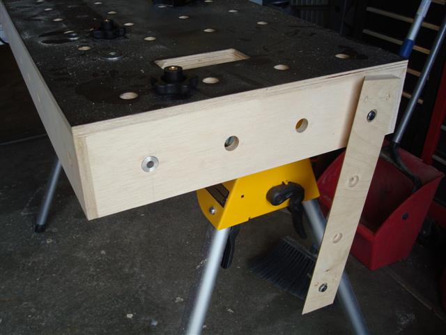
And modified a french cleat to have the same 4 inch wide hole spacing as the MFT's holes so I could attach the cleat to the table in any of the locations where holes exist.
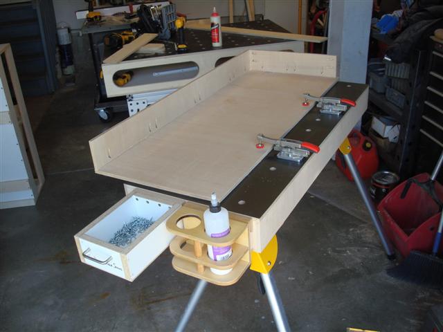
And now I can hang my tools, accessories, and other odds and ends off the side of the table so they're not taking up space.
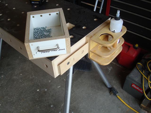
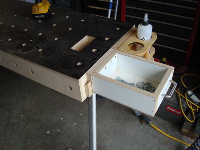
Since all of my screw boxes have cleats off the back of them they can also hang off the side which keeps them easily accessible during assembly but not actually on the work surface which is really nice.
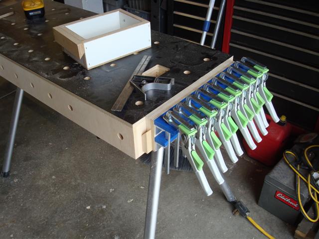
And I had to make a slight tweak to the Festool clamp rack I had previously made so it would sit nice and flush with the work surface. Now I can move the whole rack to the table and it's easier to get them out of the way instead of clamping them to the table itself.
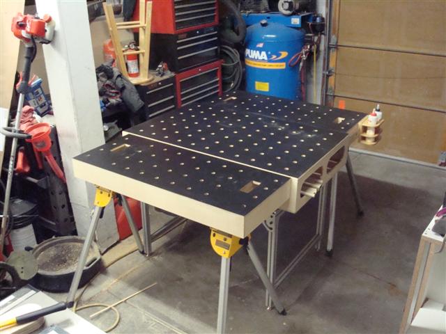
With the luxury of having more space I can now assemble the second one by using the first one. Having the MFT and the MFT-Horse I can now machine on one and assemble on the other which prevents me from moving things around during assembly - extremely nice.
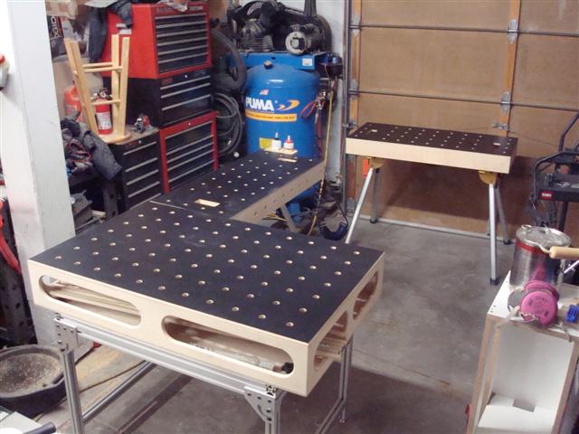
As soon as the second one is finished I played with a couple of different setups. Here's one clamped on either side of the MFT if I need a bigger table.
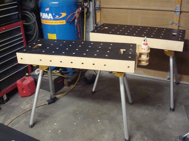
After moving them around a couple of ways this is what I think is the most likely configuration for most projects.
Talk about getting side-tracked. I started off wanting to work on the long MFT frame and instead I ended making a pair of smaller tables. I'm a little disappointed I didn't think of building them in the first place.
My initial thought was a pair of 2x4's trimmed to the right height and a piece of ply for a work surface. One of my character flaws is I can turn any 15 minute project into an all day project. I found out I didn't have even 6-inches of a 2x4 so I started fiddlin' around and when I was done, I had essentially built another MFT. The oblong slots in the box allow me to put my hand through and squeeze the release levers so I can remove it from the saw horse. The holes were machined using my router base and peg-board trick.
I also drilled the sides and ends so I could clamp on all surfaces. I built up the base with some scrap to get the exact height (though a washer ended up being the final touch to get the exact height).
And laminated the surface like the rest of the MFT's.
Then while I was about to assemble the other top I had an idea. I made some bushings out of aluminum that fit my 3/4-inch holes.
And modified a french cleat to have the same 4 inch wide hole spacing as the MFT's holes so I could attach the cleat to the table in any of the locations where holes exist.
And now I can hang my tools, accessories, and other odds and ends off the side of the table so they're not taking up space.
Since all of my screw boxes have cleats off the back of them they can also hang off the side which keeps them easily accessible during assembly but not actually on the work surface which is really nice.
And I had to make a slight tweak to the Festool clamp rack I had previously made so it would sit nice and flush with the work surface. Now I can move the whole rack to the table and it's easier to get them out of the way instead of clamping them to the table itself.
With the luxury of having more space I can now assemble the second one by using the first one. Having the MFT and the MFT-Horse I can now machine on one and assemble on the other which prevents me from moving things around during assembly - extremely nice.
As soon as the second one is finished I played with a couple of different setups. Here's one clamped on either side of the MFT if I need a bigger table.
After moving them around a couple of ways this is what I think is the most likely configuration for most projects.
Talk about getting side-tracked. I started off wanting to work on the long MFT frame and instead I ended making a pair of smaller tables. I'm a little disappointed I didn't think of building them in the first place.