You are using an out of date browser. It may not display this or other websites correctly.
You should upgrade or use an alternative browser.
You should upgrade or use an alternative browser.
More fun with 80/20...??
- Thread starter Richard/RMW
- Start date
nclemmons
Member
Yes, I have done it. What you have drawn is fine. If they have questions, they reach out via phone or email.
Neil
Neil
tdwilli1
Member
- Joined
- Jun 12, 2014
- Messages
- 55
Dave,
How did you mount the Kreg Clamp.
Tim
How did you mount the Kreg Clamp.
Tim
Dave Lame said:Please excuse me, first time posting photos.
As requested by multitudes, photos of MFT Dog House + similar devices
Dog House: Additional, seldom used puppies in orange container to right rear.
Jig standing in middle-back of dog house locks 1515 to MFT.
[attachimg=#]
Dog House on 1515 on MFT. Note "lock" underneath 1515.
[attachimg=#]
Dog House + lamp stand to left and another to rear + battery charging station to rear + saw platform to right All on 1515.
[attachimg=#]
Another view of saw platform.
[attachimg=#]
After a number of fits and starts, I have most of my 80/20 system together. As much of it is the same (extrusions and such) as everyone else has done, I'll just concentrate on what I did differently and why I use the word system to describe it.
[attachimg=#]
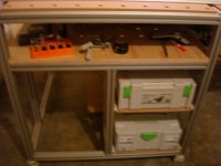
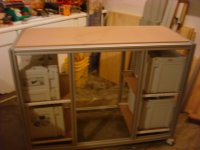
The basics are I used 40 series extrusions and carrymaster casters. On the main table I have a full shelf underneath the top to allow access to the underside of the top and to keep items I'm using at the time. For the shelves below, I chose to keep them open with the drawer glides attached directly to the extrusions. They become structural members as if the worktable needed to be any more stable. Eventually, I'll probably make drawers to go in the center section.
[attachimg=#]
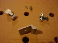
This image shows the connectors I used. The m4 screws and drop in T nuts are to mount the drawer slides. I mainly used the end fasteners on the right wherever a fixed connection was needed. I used the anchor fasteners on the left when a piece of extrusion might need to be moved or added temporarily (you'll see what I mean in a few minutes). I used the panel brackets to support the top. This is the main feature I hadn't seen anyone else describe using.
[attachimg=#]
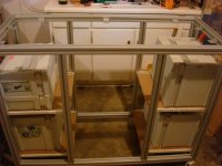
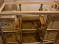
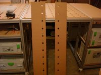
Here is a more open look at the second unit I built which has the same long length as the first but is only half as wide. You can see how the panel brackets are attached.
[attachimg=#]
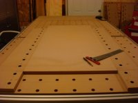
To get the top to sit up from the extrusions, I built a frame from 3/4 ply and used loose dominoes as connectors.
[attachimg=#]
Then I cut the top to the exact dimensions of the extrusion arms, drop it in and tighten the connectors. I might later directly attach the top but so far it hasn't been necessary.
The rest of this is talking about how I finally made the tops.
It started from the excellent post by Michael_Swe
http://festoolownersgroup.com/festool-jigs-tool-enhancements/make-a-perfect-%27mft%27-with-qwas-raildogs/msg238735/#msg238735
[attachimg=#]
The first change I made was to make the first set of holes in jig boards instead of on the blank itself. I actually drilled both boards at the same time and flipped one.
[attachimg=#]
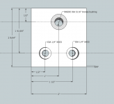
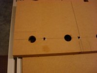
One other difference from what others have done is that I wanted the first row and column to be exactly 28 mm from the edge (more on that later). I'll also show what the 32mm offset shelf pin holes are for.
[attachimg=#]
[attachimg=#]
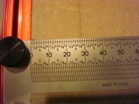
In this step and most others in making the top I don't think I can possibly overstate the importance the Incra precision T-rule has been to me. It has become a go-to tool.
[attachimg=#]
Here is my setup for drilling the top. Keeping the jig precisely aligned was critical so I used three bar clamps so I could always have at least two attached at all times.
[attachimg=#]
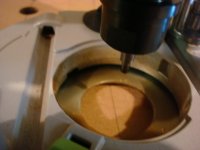
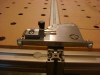
Probably the most controversial (heretical?) thing I did was to precisely drill a hole in the rail to fit the pin hole in the jig to get that 28 mm distance from the side. I used this as a coarse adjustment that I refined later.
[attachimg=#]
[attachimg=#]
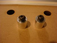
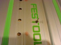
I also couldn't overhang the side guide holes to use the Qwas rail dogs and keep everything stable while drilling. So I used these threaded sleeves I got from John at tool improvements. They let me work on a flat tabletop. I don't know of anyone currently making these but as they make excellent rail pups I would expect that any of the current dog suppliers could make a set.
[attachimg=#]
[attachimg=#]
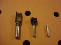
For the drilling operation I used three bits. The first is a Whiteside 25/32, second the Festool 20 mm, and finally a pin I had on hand which is part of the Micro Fence circle jig. This made for a lot of bit change out during the process but as they each used a different collet, the process went fairly smoothly. At the start of each row I used the centering pin to make a fine adjustment then clamped the rail and removed the shelf pin from the rail. I used the Whiteside bit which was slightly undersized to remove most of the material. I found best results at not drilling completely through with this bit even using a backer board. I have a bias toward using a 1/2 inch shank when drilling through thick material. I then used the 20 mm to size the holes and make a clean exit through the board.
Then wash, rinse and repeat and you have a board full of holes.
Now I have two tables, one with a holy top and one without. Here comes the system part.
[attachimg=#]
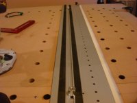
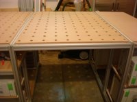
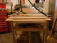
By simply using two more pieces of extrusion and a second drilled top flipped with respect to the other, I now have a top that is a little over 4 by 8 feet.
[attachimg=#]
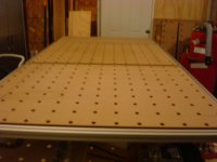
Looking down the line you can see what I was hoping for.
[attachimg=#]
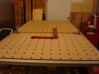
First, it passed the square test.
[attachimg=#]
Second the other thing I was trying for worked as well. If you had been doing the math you would have seen that 28 mm times two plus a 40 mm extrusion gives a 96 mm hole space between tops. The only thing I had to demonstrate this was this part from my MFT 1080s.
[attachimg=#]
Now it is time to get to work. But as you can see, the next top I build will be much easier.
Sorry this was so long but I hope you found the read worthwhile.
Dick Perry
[attachimg=#]
The basics are I used 40 series extrusions and carrymaster casters. On the main table I have a full shelf underneath the top to allow access to the underside of the top and to keep items I'm using at the time. For the shelves below, I chose to keep them open with the drawer glides attached directly to the extrusions. They become structural members as if the worktable needed to be any more stable. Eventually, I'll probably make drawers to go in the center section.
[attachimg=#]
This image shows the connectors I used. The m4 screws and drop in T nuts are to mount the drawer slides. I mainly used the end fasteners on the right wherever a fixed connection was needed. I used the anchor fasteners on the left when a piece of extrusion might need to be moved or added temporarily (you'll see what I mean in a few minutes). I used the panel brackets to support the top. This is the main feature I hadn't seen anyone else describe using.
[attachimg=#]
Here is a more open look at the second unit I built which has the same long length as the first but is only half as wide. You can see how the panel brackets are attached.
[attachimg=#]
To get the top to sit up from the extrusions, I built a frame from 3/4 ply and used loose dominoes as connectors.
[attachimg=#]
Then I cut the top to the exact dimensions of the extrusion arms, drop it in and tighten the connectors. I might later directly attach the top but so far it hasn't been necessary.
The rest of this is talking about how I finally made the tops.
It started from the excellent post by Michael_Swe
http://festoolownersgroup.com/festool-jigs-tool-enhancements/make-a-perfect-%27mft%27-with-qwas-raildogs/msg238735/#msg238735
[attachimg=#]
The first change I made was to make the first set of holes in jig boards instead of on the blank itself. I actually drilled both boards at the same time and flipped one.
[attachimg=#]
One other difference from what others have done is that I wanted the first row and column to be exactly 28 mm from the edge (more on that later). I'll also show what the 32mm offset shelf pin holes are for.
[attachimg=#]
[attachimg=#]
In this step and most others in making the top I don't think I can possibly overstate the importance the Incra precision T-rule has been to me. It has become a go-to tool.
[attachimg=#]
Here is my setup for drilling the top. Keeping the jig precisely aligned was critical so I used three bar clamps so I could always have at least two attached at all times.
[attachimg=#]
Probably the most controversial (heretical?) thing I did was to precisely drill a hole in the rail to fit the pin hole in the jig to get that 28 mm distance from the side. I used this as a coarse adjustment that I refined later.
[attachimg=#]
[attachimg=#]
I also couldn't overhang the side guide holes to use the Qwas rail dogs and keep everything stable while drilling. So I used these threaded sleeves I got from John at tool improvements. They let me work on a flat tabletop. I don't know of anyone currently making these but as they make excellent rail pups I would expect that any of the current dog suppliers could make a set.
[attachimg=#]
[attachimg=#]
For the drilling operation I used three bits. The first is a Whiteside 25/32, second the Festool 20 mm, and finally a pin I had on hand which is part of the Micro Fence circle jig. This made for a lot of bit change out during the process but as they each used a different collet, the process went fairly smoothly. At the start of each row I used the centering pin to make a fine adjustment then clamped the rail and removed the shelf pin from the rail. I used the Whiteside bit which was slightly undersized to remove most of the material. I found best results at not drilling completely through with this bit even using a backer board. I have a bias toward using a 1/2 inch shank when drilling through thick material. I then used the 20 mm to size the holes and make a clean exit through the board.
Then wash, rinse and repeat and you have a board full of holes.
Now I have two tables, one with a holy top and one without. Here comes the system part.
[attachimg=#]
By simply using two more pieces of extrusion and a second drilled top flipped with respect to the other, I now have a top that is a little over 4 by 8 feet.
[attachimg=#]
Looking down the line you can see what I was hoping for.
[attachimg=#]
First, it passed the square test.
[attachimg=#]
Second the other thing I was trying for worked as well. If you had been doing the math you would have seen that 28 mm times two plus a 40 mm extrusion gives a 96 mm hole space between tops. The only thing I had to demonstrate this was this part from my MFT 1080s.
[attachimg=#]
Now it is time to get to work. But as you can see, the next top I build will be much easier.
Sorry this was so long but I hope you found the read worthwhile.
Dick Perry
Attachments
-
 11.JPG103.6 KB · Views: 4,627
 -
 12.JPG110.8 KB · Views: 4,407
 -
 13.JPG97 KB · Views: 4,371
 -
 14.JPG95.5 KB · Views: 4,364
 -
 15.JPG96.7 KB · Views: 4,912
 -
 16.JPG98.8 KB · Views: 4,365
 -
 17.JPG99.4 KB · Views: 4,513
 -
 18.JPG107.3 KB · Views: 5,183
 -
 19.JPG108.7 KB · Views: 4,679
 -
 10.JPG100.8 KB · Views: 4,654
 -
 9.JPG113.2 KB · Views: 4,619
 -
 1.JPG107.9 KB · Views: 4,833
 -
 2.JPG107.2 KB · Views: 4,799
 -
 3.JPG114.6 KB · Views: 4,986
 -
 4.JPG100.6 KB · Views: 4,740
 -
 5.JPG109.6 KB · Views: 4,856
 -
 6.JPG101.7 KB · Views: 4,616
 -
 7.JPG106.3 KB · Views: 4,310
 -
 8.JPG109 KB · Views: 4,380
 -
 8a.JPG97.7 KB · Views: 4,867
Richard/RMW
Member
- Joined
- Jul 11, 2010
- Messages
- 2,947
Dick,
Awesome job! Thanks for documenting it so thoroughly, the text/photos make it a cinch to understand exactly what you did.
I have nowhere near the space to work with but am hoping to get back to my own, much smaller, 80/20 MFT project soon.
Thanks for sharing, you are going to love working on that setup.
RMW
Richard,
The main reason I started on this project is that I consider my workspace small as well, around 16x16 feet. I don't intend for the large unit shown above to be set up very often. The small table and another I have planned that has the same width as the small one but the length of the short side of the main table will replace the ugly white thing shown in some of the shots above. I also plan to put my planner and possibly some other smaller tools on their small table tops.
80/20 refers to their product as being the industrial erector set and I hope to take advantage of that to roll together what I need at the time and leave them against the wall when I don't. This is however turning into another addiction.
Dick
Richard/RMW
Member
- Joined
- Jul 11, 2010
- Messages
- 2,947
16' by 16', 256 SF... I would kill for that enormous space... [poke]
@ 10 by 12 outside dimension I am constantly struggling to find a place for [insert tool type here].
Seriously though, it has made me think thru what I really need to do the work I want to. I started w/ Festool when we moved to this house, going from a 800 SF shop to this little shed. Forced me to get rid of all my stationary tools other than a couple of small benchtop items.
One way I made it work larger is having the outside deck at the same height, weather permitting I can roll everything outside.
[attachthumb=1]
I spent the last couple days staring at my MFT, which has been covered with grill racks and accessories for the past couple weeks. Came to the realization that it takes up a lot of SF (nearly 9 of < 120) and I have not actually cut anything on it recently. Now I am noodling a hybrid, something that is only 20" deep with a top that expands.
Yes, the erector set does become addicting. [doh]
RMW
Attachments
![ScreenClip [14].png](/data/attachments/8/8508-1df5e3cfad26225d7e6f9617edec6164.jpg?hash=I3Jckn1Hrx)
elfick,
I agonized over that part of the setup for quite a while. In the end I had to have the vertical slots in the legs available to be able to add the middle section. You can see that in the next to last picture.
To make up for that I stocked up on what they call roll-in T-nuts especially the ones with a shoulder and a ball spring. And as I talked about with the drawer slides I use drop in T-nuts that twist to lock. This lets me add things after final assembly. Among other things, I hope to add a Moxon vise to one end of the main table but still be able to remove it.
Richard,
My 16x16 is also outside dimensions with six inch walls. Makes me feel squeezed in when I think of it that way.
I also do without a table saw and made the tables so beefy so I can do hand planning and the like on them as well.
Dick
Richard/RMW
Member
- Joined
- Jul 11, 2010
- Messages
- 2,947
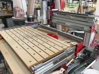
Came up with this as a quick setup for cutting sheet goods or dimensional stock:
[attachthumb=1]
[attachthumb=2]
[attachthumb=3]
Toying with the idea of combining the 2 Dewalt horses with more/longer extension arms and making an "L" shaped work area.
RMW
[attachthumb=1]
[attachthumb=2]
[attachthumb=3]
Toying with the idea of combining the 2 Dewalt horses with more/longer extension arms and making an "L" shaped work area.
RMW
Attachments
![ScreenClip [17].png](/data/attachments/8/8546-2ac59910c0351a5dd1f28eaf6bec2c55.jpg?hash=8nRiRqclcj)
![ScreenClip [16].png](/data/attachments/8/8545-9d918fca5f8495033d8773e7fc141c36.jpg?hash=mImn-xV96A)
![ScreenClip [18].png](/data/attachments/8/8544-20874c5df2d58cdc11e26576f5c127d4.jpg?hash=aKJ20yQVzu)
Richard/RMW
Member
- Joined
- Jul 11, 2010
- Messages
- 2,947
Oso Rojo said:Nice setup. How did you connect the rails to the Dewalt guide?
Thanks. Made some T-nuts from 1/4" AL bar w/ hole tapped 5/16", they fit in the slot of the Dewalt horse.
RMW
Richard/RMW said:I spent the last couple days staring at my MFT, which has been covered with grill racks and accessories for the past couple weeks. Came to the realization that it takes up a lot of SF (nearly 9 of < 120) and I have not actually cut anything on it recently. Now I am noodling a hybrid, something that is only 20" deep with a top that expands.
Yes, the erector set does become addicting. [doh]
RMW
I have been toying with same idea for my shop. I have a floorspace of 9-1/2 feet by about 18 feet. One wall has my lumber rack so about 1-1/2 of floor space and wall space for tools is lost. I am coming to the conclusion that my MFT's take up a lot of working around space. I have been watching this conversation with a lot of interest along with a couple of others threads discussing variations to Ron Paulk's design.
RMW's idea for integrating DW rail and 80/20 really rang my bell. The same idea could be used to extend my further replacement of MFT as well as moving outside to my 1/2 acre shop for projects that are too big for inside my shop. Even if I have space horizontally to build inside, my ceiling is less than 6'8" high. A set of shelves or a cabinet of any size are almost impossible to construct the way I am presently set up.
Tinker
Richard/RMW
Member
- Joined
- Jul 11, 2010
- Messages
- 2,947
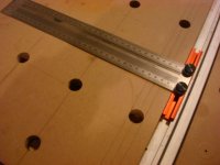
While I love my MFT and have a lot invested in dogs, etc. I am realizing it gets used for cutting only infrequently. Anytime I am cutting plywood I default to the 80/20 extensions with parallel guides for ripping, and this t-square-ish guide for cross cutting:
[attachthumb=1]
[attachthumb=2]
[attachthumb=3]
Sometime after the first photos were taken I modified it by adding a section of Incra T-Track + with an adjustable stop, this lets me set repeatable panel lengths between about 9.5" and 24". Anything longer I just measure/mark and align the splinter guard.
[attachthumb=4]
My current weekend project is a weatherproof storage area under the deck off the house, it gives me about 7' wide by 9' long, 36" high storage for materials and some tools. Basically built a very short shed under the deck. When completed next weekend I suspect my MFT will be calling it home, then I can figure out what to replace it with inside the shop.
RMW
Attachments
![ScreenClip [21].png](/data/attachments/8/8616-edc0b0752ffc7c16fedccd81a64d8d4c.jpg?hash=5_ZryOIQpW)
![ScreenClip [20].png](/data/attachments/8/8617-69d6ceffd9a88b2bcb5bf6d7d5bb4366.jpg?hash=kiehBHVAME)
![ScreenClip [22].png](/data/attachments/8/8618-36ec5aeac41e025b333e12c35d546b75.jpg?hash=R3pvjIbcTE)
![ScreenClip [23].png](/data/attachments/8/8619-1d7713d6e58ae841066242aedfe93bbe.jpg?hash=K940Rgslv8)
promark747
Member
- Joined
- Jan 9, 2010
- Messages
- 469
Richard/RMW said:Oso Rojo said:Nice setup. How did you connect the rails to the Dewalt guide?
Thanks. Made some T-nuts from 1/4" AL bar w/ hole tapped 5/16", they fit in the slot of the Dewalt horse.
RMW
When you have a chance, can you please take a pic of those T-nuts?
Thanks
Richard/RMW
Member
- Joined
- Jul 11, 2010
- Messages
- 2,947
promark747 said:Richard/RMW said:Oso Rojo said:Nice setup. How did you connect the rails to the Dewalt guide?
Thanks. Made some T-nuts from 1/4" AL bar w/ hole tapped 5/16", they fit in the slot of the Dewalt horse.
RMW
When you have a chance, can you please take a pic of those T-nuts?
Thanks
[member=7714]promark747[/member]
I'll see if I can find them, they were basically just 1-1/2" squares of 1/4" AL with a 5/16" hole centered and tapped. I think I ground a slight bevel on 2 edges to match the underside bevel on the DeWalt horses.
Needed to cut some ply recently and I almost dug them out but instead used those 80/20 extension arms on the MFT to create a surface for cutting full sheets down.
RMW
ryanjg117
Member
- Joined
- May 18, 2015
- Messages
- 328
Figured you 80/20 fans would like this one:http://festoolownersgroup.com/workshops-and-mobile-vehicle-based-shops/repurposed-a-$10-000-custom-solar-panel-conveyor-into-tablesaw-outfeed-table/
Similar threads
- Replies
- 2
- Views
- 310
- Replies
- 4
- Views
- 414
- Replies
- 2
- Views
- 1K
- Replies
- 30
- Views
- 2K