Crazyraceguy
Member
- Joined
- Oct 16, 2015
- Messages
- 4,914
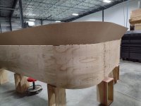
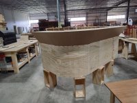
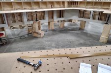
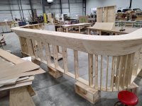
So, I have this reception desk job in the shop, with a partially angled section of the exterior wall. The tricky part is that is has radiused corners. Angle and radius works out to be a segment of a cone.
How do you wrap a cone with plywood? Kerf cutting, not the "easy way" (which is not really as easy as it sounds either) but it needs to be tapered.
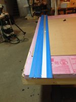
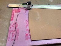
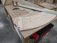
Back in the day, I did learn some long formula to figure out that shape. Today we have the interwebs and some nice person figures this out for you and makes an app for that. Put all of that into the CNC machine and out comes the C shapes, but it still won't bend. How to Kerf it? Track saw. I made a jig to hold the parts with a pivot point to swing the track from.
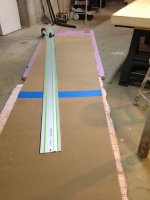
I had to be adjustable enough to cover the two different radii on this job. I made the stops that hold the parts removeable, because of the 2 different sizes. Simple plywood strips with a couple of Dominos worked well.
I suppose that you could do the kerf cuts on the CNC, but that would take forever. Sawing is far better for this many narrow cuts that nearly go all of the way through 3/4" plywood.
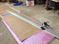
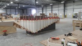
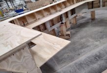
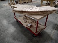
With this jig, I cut 48 separate kerfs in less than 10 minutes, in some of the parts, and 43 cuts in the others. Altogether that came out to 556 cuts, 48 yesterday, when this was a proof-of-concept test and 508 today. Yes, 8 of the one size and 4 of the other.
Apparently, I didn't take a pic of it with the saw actually on the track? but here is the jig and the cut parts. More to follow as the job develops.
How do you wrap a cone with plywood? Kerf cutting, not the "easy way" (which is not really as easy as it sounds either) but it needs to be tapered.
Back in the day, I did learn some long formula to figure out that shape. Today we have the interwebs and some nice person figures this out for you and makes an app for that. Put all of that into the CNC machine and out comes the C shapes, but it still won't bend. How to Kerf it? Track saw. I made a jig to hold the parts with a pivot point to swing the track from.
I had to be adjustable enough to cover the two different radii on this job. I made the stops that hold the parts removeable, because of the 2 different sizes. Simple plywood strips with a couple of Dominos worked well.
I suppose that you could do the kerf cuts on the CNC, but that would take forever. Sawing is far better for this many narrow cuts that nearly go all of the way through 3/4" plywood.
With this jig, I cut 48 separate kerfs in less than 10 minutes, in some of the parts, and 43 cuts in the others. Altogether that came out to 556 cuts, 48 yesterday, when this was a proof-of-concept test and 508 today. Yes, 8 of the one size and 4 of the other.
Apparently, I didn't take a pic of it with the saw actually on the track? but here is the jig and the cut parts. More to follow as the job develops.
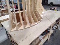
 . How deep are those kerfs, there can’t be more than .030” of skin left? Are there any lines telegraphing through?