Nothing special, just a particleboard Sysport

squall_line

Member
Joined
Feb 17, 2021
Messages
2,921
I've mostly been using my tools for "handyman" work, tearing out an old deck, cutting out a vinyl tub, etc, and I used my HK55 early last year to build out a reclaimed bookshelf, but I think this is my first "real" project with my Festool kit.  Only took me 20-ish months to start to use them...

I tend to wait until I'm almost done to post anything, which ends up garnering fewer views and comments, and this time is no exception.  I also don't take many pictures as I'm going unless I'm texting my brother to keep him up to date on my progress or if I run into an issue that I need to research further.

So, this is a smattering of "in progress" photos of a three-wide sysport build out of pre-drilled particleboard shelving pieces from Menards.

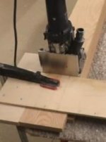
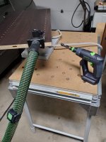
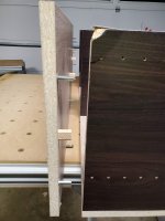
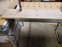
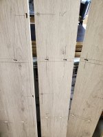
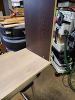
I first cut the sides to length on my MFT with the Dashboard PWS rail hinge.  Once I got the fence locked in square, the flag stop made repetitive cuts easy and consistent, although I was still paranoid.

[attachimg=1]
[attachimg=2]

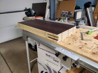
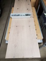
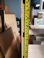
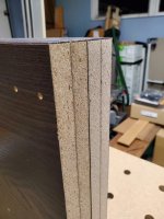
One of the three shelves was a different depth than the other two (note for the future: check this before you take it to the counter and all the way home).  I needed stretchers for the back, so I ripped the narrower shelf down the middle.  It also turns out that piece was only square on the edge-banded faces, so this gave me two pieces with a good square edge to register at the top and bottom when using it as a stretcher.

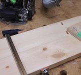
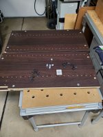
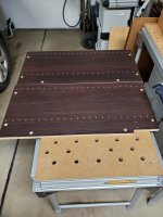
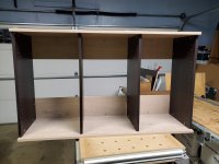
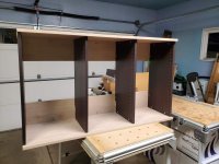
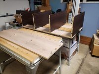
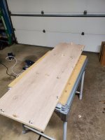
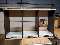
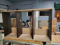
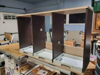
I decided to go with a three-wide port for my first ever big build and also the KV D8 knockdown connectors because apparently I'm a glutton for punishment and wanted to try all sorts of new-to-me techniques all in the same project.  I cut the top and bottom a few millimeters long in case the sides weren't a consistent thickness.  Here's a mockup before any mortising with SYS-AZ drawers in place to gut-check everything.

[attachimg=3]

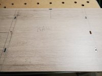
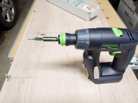
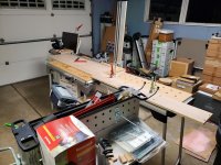
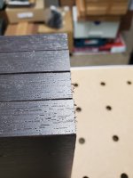
Did a quick practice run with the remaining scraps to work out the mortising and drilling techniques and order of operations for using the D8 knockdown connectors.

[attachimg=4]

I had issues with the centeredness of the extensions on my domino on my last project, and I don't fully trust the paddles to be centered, but the sight window/line is reliable for me, so I chose to mark out mortises at 50mm instead of the typical 37mm from the paddles, and then centered around 201mm for a center mortise.  The 200mm pocket-T square made these markings trivially repeatable.  I occasionally used the marking guides on the 1282SS as well.  My eraser will get a very good workout after this!

[attachimg=5]

[attachimg=7]

[attachimg=8]

"Order of operations" is the biggest name of the game at this point... With dominos in all directions, I had to be deliberate about which order I assembled so as to prevent interference on fitting everything.  I almost punted and pulled out the Zeta P2 to reduce protruding depth for assembly, but it was one more learning curve that I didn't want to try to throw in the mix this time around.

Considering all of the mortises were cut at the narrowest width, I was still able to dry fit everything together, which I credit fully to the accuracy and repeatability of the measuring/marking tools instead of eyeballing and marking with a tape measure.

[attachimg=6]

Next up (tonight?) is drilling all of the grub screw openings for the connectors, which already sounds tediously relaxing, like all of the erasing I still need to do, and pre-drilling for the cabinet feet.
 

Attachments

  • 20221025_210628.jpg
    20221025_210628.jpg
    339.2 KB · Views: 734
  • 20221114_205538.jpg
    20221114_205538.jpg
    335.3 KB · Views: 698
  • 20221114_205529.jpg
    20221114_205529.jpg
    357.7 KB · Views: 707
  • 20221114_211857.jpg
    20221114_211857.jpg
    393 KB · Views: 699
  • 20221114_222632.jpg
    20221114_222632.jpg
    856.3 KB · Views: 707
  • 20221111_142124.jpg
    20221111_142124.jpg
    379.3 KB · Views: 702
  • 20221111_203913.jpg
    20221111_203913.jpg
    359.4 KB · Views: 737
  • 20221025_210642.jpg
    20221025_210642.jpg
    243.3 KB · Views: 732
How did you do the mid-panel mortises? Freehand or with a jig?[attachimg=1]
 

Attachments

  • df mid panel q.JPG
    df mid panel q.JPG
    60.4 KB · Views: 670
ChuckS said:
How did you do the mid-panel mortises? Freehand or with a jig?[attachimg=1]

I did all them free-jig-hand?

By that, what I mean is that I used the mating shelf as a backstop and registered off the base, which slightly off-sets the dominos in the 19mm stock but keeps them properly registered as long as you line the crossing piece up correctly with your location.

As seen around 1:30 in this halfinchshy video:
=89

Or in this Sedgetool video:


Main difference on what I did compared to both of them was that I scribed layout lines on both pieces instead of only the shelf, and I didn't use the flaps for registration.  I used my 1282 to square them up before clamping.  Part of why I used the lines was because then I also didn't have to worry about keeping everything lined up while I cut the mortises, I just used the pieces as each others' fence and lined up the cursor on the line (even with a dark surface, a pencil shows up as silver and is pretty easy to find in the window).

On the ends, I used the more typical registration from the edge and the outside, using the fence and the stock plastic foot.

On the stretchers, I used the fence on the MFT to hold the stretcher in place while I put the panel over it and used a scrap to keep the panel flat.

With all of the labeling that you see, I worked project-Left to project-right on the top, bottom, and stretchers, and only did one part at a time.  In the future, I may modify the order of work for the mortises, but probably not the technique.  I probably also won't' do a three-bay unit again; two bays would be much less hassle and measuring.

I tossed the cord and hose over my shoulder like an anaconda to keep them from screwing everything up.  Eventually I would like to go to a boom or hanging hose, but alas.
 
You didn't show the dividers on the top/bottom in your before-assembly photos, so I thought you used something else to mortise the top & bottom pieces, such as a T-Square like jig so you didn't have to handle the (dark brown) shelves for each cut:

[attachimg=1]


Attachments

  • DF mid-panel mortise jig.JPG
    DF mid-panel mortise jig.JPG
    14.4 KB · Views: 625
ChuckS said:
You didn't show the dividers on the top/bottom in your before-assembly photos, so I thought you used something else to mortise the top & bottom pieces, such as a T-Square like jig so you didn't have to handle the (dark brown) shelves for each cut:

[attachimg=1]

Ahh, good point.

The dark brown pieces have just as many, if not more, lines and mortises.  I definitely handled them for each section, if for no other reason than to ensure everything flowed correctly, especially since some of the pieces came pre-cut to fit over trim, leading to different domino spacing for the stretchers. 

[attachimg=1]

A jig like the one you showed would probably make things move much more quickly in the future.
 

Attachments

  • 20221114_222410.jpg
    20221114_222410.jpg
    335 KB · Views: 638
Yes, the jig approach is good for multiple shelving. You can also use it (jig fence at an angle instead of at 90*) to do angled mortises:[attachimg=1]

Lining up and marking shelves at an angle can be very time-consuming.
 

Attachments

  • DF angle guide.JPG
    DF angle guide.JPG
    37.5 KB · Views: 629
squall_line said:
Snip.

  I definitely handled them for each section, if for no other reason than to ensure everything flowed correctly, especially since some of the pieces came pre-cut to fit over trim, leading to different domino spacing for the stretchers. Snip.
You did well as the nature of such operation (many identical or similar boards and many mortises to be milled on each board) made it  error-prone.
 
I busted out the Vac-SYS and batched out all of the 15mm access holes for the set screw receivers in pretty short order.  Using the Vac-SYS on the MFT-Kapex made the working height almost perfect, even if it's not low enough to rest on a standard MFT.

[attachimg=1]

[attachimg=2]

Inserted all of the connector hardware and locked in the expanders before spinning the posts back out to make it safer/easier to move the parts around.

[attachimg=3]

[attachimg=4]

Used a tip from a Festool LIVE episode where Sedge pointed out that the posts are a standard 1/4" hex and fit in the bit holder; this made locking in the expanders pretty quick and painless, as well as backing the posts out again.

[attachimg=5]

[attachimg=6]

I finally busted out the eraser and cleaned off all of the layout lines other than the "Top" and "Bottom" words to keep myself sane.  There are some markings on the top of each of the upright rails to keep them in order, too.  The erasure was almost worse on my arms and shoulders than any of the parts lifting that I had done so far.

Project is on hold for a day or two until I can work out an issue with the legs that I bought for the base.  Another lesson in "check the packaging before you check out, especially if it looks like it's been taped closed."
 

Attachments

  • 20221115_220644.jpg
    20221115_220644.jpg
    471.1 KB · Views: 607
  • 20221115_220424.jpg
    20221115_220424.jpg
    190.9 KB · Views: 606
  • 20221115_215526.jpg
    20221115_215526.jpg
    248.1 KB · Views: 615
  • 20221115_214745.jpg
    20221115_214745.jpg
    504.1 KB · Views: 616
  • 20221115_214112.jpg
    20221115_214112.jpg
    485.9 KB · Views: 613
  • 20221115_212811.jpg
    20221115_212811.jpg
    369.4 KB · Views: 614
Got sidetracked by the holidays and other projects around the house, and went back to work on this last night.

I went for assembly but most of the posts didn't want to go into the holes.  It turns out I didn't drill most of the 15mm holes deep enough for the capture nuts.  Apparently I was stopping once I broke through into the tenon entry, but the bit needs to bottom out on the bearing to counter-sink the capture piece enough to center it.

Luckily, the 3mm driver that comes with the set makes for a decent little hook tool to remove all of the plastic holders and pop out the capture nuts.  It was too late by the time I got those all backed out to want to set up the Vac-SYS and re-drill the holes, so this is once again on hold, but hopefully only until later tonight.
 
Be aware that many/most erasers contain silicone. That might or might not be a problem in your case when it comes to applying finish. It is why I stopped using them and use acetone nowadays to remove my pencil markings. That works quite well for me.
 
hdv said:
Be aware that many/most erasers contain silicone. That might or might not be a problem in your case when it comes to applying finish. It is why I stopped using them and use acetone nowadays to remove my pencil markings. That works quite well for me.

Good point, for sure!

In this case, the particleboard already has patterned faces, so no finishing is planned.  If I was using bare wood, I would likely have used 180 or 220 to get out the pencil marks (and likely wouldn't have applied them quite as liberally in the first place).
 
Where did I leave off?

Oh, that's right, deepening the holes and the final assembly.

Pulled out the Vac-SYS to touch up all of the set screw access holes, which went pretty quickly.

Next, get all of the dominoes into place as well as the posts for the knockdown connectors.  Especially important in this step is to make sure that the connectors are facing in the correct direction to accept the set screw.

[attachimg=1]

I had already lined up and set the top stretcher in place, finger-tightening the set screws.  My plan was to set the top piece on the MFT-Kapex, which is a few inches lower than the MFT/3, and then lift/rotate the entire carcass onto the top.

[attachimg=2]

This idea proved to be unwieldy and just plain silly in retrospect.  I move the MFT-Kapex to the other side of the garage and opened up another MFT/3 to set the top on, and then rotated the top up into place and tried to get it all assembled.

[attachimg=3]

[attachimg=4]

I had cut EVERYTHING with a narrow mortise, so I got the right (as I stood) side partially engaged, then moved toward the left, engaging a little bit of each domino as I went to allow everything to slip together.  And then the right-hand side popped out.  So I moved back and the left side popped out.

I eventually found the culprit, which was pretty obvious in retrospect when looking down the row of panels.  The mortise on this panel should have been centered 172mm from the front of the panel or 183mm from the back (the front is at the top of the picture). I always measured from both directions and just split the pencil line with the domino cursor to account for any variation on the front or back of the panel.

[attachimg=5]

I pulled the domino out, dropped the panel on the Vac-SYS (luckily it was still out from drilling the access holes), and put the mortise where it needed to be.  It was now significantly wider than it needed to be, but I didn't back fill it because it's just helping keep the top from racking, along with the two knockdown posts and the back stretcher. 

With the mortise re-cut, everything went together much more smoothly (ignore the damage where the panel fell out during dry fit).

[attachimg=6]

I rotated the cabinet around, did the same procedure with the back stretcher and base on the bottom of the cabinet, and finally stood the whole thing up on an MFT to prepare for Sys-AZ installation.

[attachimg=7]

[attachimg=8]

Finally installed the lowest row of Sys-AZ drawers and called it a night.  It's much shorter than I anticipated, so I need to plan out the heights for the remaining drawers once I figure out what's going in those slots.

[attachimg=9]

Out of the dozens (76 total?) of the mortises I cut, all at a narrow setting, I only ended up with a single mortise that was mis-aligned, and it was caused by a measuring error rather than a technique or machine error. [eek]  I'm wearing that badge proudly until it comes back to bite me on a future project.

Also, this thing is stupid heavy and awkward.  My next two cabinets will be the same style but only two ports wide, which will use slightly more material but should be a little less awkward to move around.  They will also receive legs and serve as the base under this cabinet, which I have already notified my wife she may need to help me lift.
 

Attachments

  • 20221202_220118.jpg
    20221202_220118.jpg
    241.4 KB · Views: 292
  • 20221202_220122.jpg
    20221202_220122.jpg
    235.4 KB · Views: 241
  • 20221202_213444.jpg
    20221202_213444.jpg
    240.6 KB · Views: 240
  • 20221202_212410.jpg
    20221202_212410.jpg
    423.7 KB · Views: 243
  • 20221202_211936.jpg
    20221202_211936.jpg
    227.5 KB · Views: 269
  • 20221202_211904.jpg
    20221202_211904.jpg
    305.5 KB · Views: 243
  • 20221202_211340.jpg
    20221202_211340.jpg
    311.8 KB · Views: 250
  • 20221202_211317.jpg
    20221202_211317.jpg
    449.8 KB · Views: 245
  • 20221202_221552.jpg
    20221202_221552.jpg
    242.4 KB · Views: 243
I built all of mine as individual units. It does take a lot more material that way, more sides. I also made them wider that they need to be, so when I build the new ones for the home shop, they will change some. I might go with the pockets routed into the pull-outs, to keep the Systainers from moving, rather than the way they are now.
I need to think more about space conservation at home, but I still like the idea of individual units for modularity. I kind of expect to do some reconfiguring after I get it all in place and work with it for a while.
 
Back
Top