smorgasbord
Member
An old review of a protractor devolved into a discussion of how to obtain non-standard angles (which are 22.5º, 30º, 45º, 60º nor 90º) with a high degree (pun intended) of accuracy. I'm moving that discussion to its own thread here.
There are various digital angle "finders" available, but their accuracy is at best +/- 0.1º. Most are worse at +/- 0.2º. For some purposes, that may be accurate enough, but for others, such as making a wide pentagonal frame, even just 1/10º off means there's a full degree of gap in the frame. And while trial and error techniques can enable us to sneak up on accurate angles, or the use homemade guides/templates that are flipped to remove the gap at the price of a small misalignment, there are some projects (tapered boxes is the obvious one), where those techniques can be difficult. Note that the digital inclinometers currently favored by YouTubers also have accuracy of only +/-0.2º - worse than the better finders (protractors).
Before John Economaki retired and sold Bridge City Tool Works to Harvey Tool, he made two versions of an "Angle Master Pro" device that used a caliper to dial in (pun intended) accurate angles. The AMPv2 was reviewed by [member=3513]PaulMarcel[/member] here (blog and video). The AMPv2 sometimes shows up second hand for about $300 or so, but that's rare and even then, expensive.
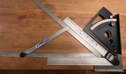
I was pointed at the Shinwa Sliding Bevel by [member=74278]Packard[/member]. Like the AMPv2, it uses the Law Of Cosines to produce angles based on the length of 3 sides of a triangle. I bought the largest one Shinwa makes on Amazon for about $60. Here's what it looks like:
[attachimg=1]
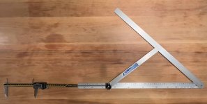
I don't have an uber-accurate way to measure angles where I'm at right now. For grins, I've been playing around with the Shinwa, a Wixey digital finder, my old AngleWright (also not made, probably accurate to 1/10º at least but not much better), and a DIN-rated square. Here they are nested at 40/50 degree angles (not a good way to test, though):
[attachimg=2]
For $60, the Shinwa seems pretty good for angles between about 20º and 120º (the closer you get to the middle the more accurate it seems to be). But, it seems to be made for carpenters cutting rafters and such - it can be used like a larger, more accurate speed square to guide circular saws cutting 2X lumber.
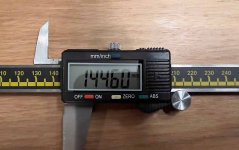
But, the design using the LOC (Law Of Cosines) has much more accuracy potential. One problem is that, due to the cosine function, the angle markings along one arm are not evenly spaced. This makes obtaining angles like 43.7º difficult since you have to interpolate 7/10 of the way between 43º and 44º. Now, there is a metric scale along the top edge that can help with interpolation (as [member=74278]Packard[/member] pointed out), but an even more accurate procedure would be to use a large caliper from the far end, then do a subtraction to get the effective arm length to plug into the LOC formula. Here's a demonstration of that setup for a 42.77º angle:
[attachimg=3]
Essentially, instead of using the metric scale on the Shinwa, use the depth rod on the caliper to get a more exact reading.
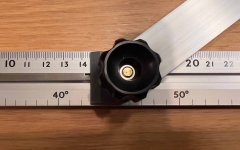
[attachimg=4]
versus
[attachimg=5]
To do this, I had to first measure the Shinwa's two fixed-length arms. This is done between the center of the pivots, since the arms are parallel to the centerline between the two pivots. The fixed middle arm is 330.0mm long, the fixed side arm is 291.0mm (as best I could measure). For the adjustable side there are a couple complications, but not too bad actually. First is that we're measuring not from the pivot but from the far end of the arm. The arm is 640.0mm from pivot to the end (as best I could measure). Second is that Shinwa uses a plastic indicator that slides in a groove along the arm, trapping the pivot and providing an edge against which to line up with the markings. I measured the distance from the edge to the center of the pivot hole at 17.5mm. Thus, the effective length is 640.0 - 17.5 = 622.5 mm.
Now we can use the LOC to get the effective length needed, which we subtract from 622.5 to obtain our caliper reading.
The example in the photos above is for 42.77º. Plug in 291.01 for side a, 330.0 for side b and 42.77 for Gamma (the angle), and side c is 477.91 mm. We subtract that from 622.5 since we're reading from the other end, and you get 144.59mm. Slide the plastic indicator against the caliper depth rod until you get that reading, and viola! you're at 42.77º. Which checks out as far as I can measure, which isn't nearly good enough unfortunately.
In evaluating the Shinwa, the plastic indicator appears to me to be its achilles heel. There's some play in the pivot hole, not quite a mm's worth. When using it to measure an existing angle, you can easily slide the plastic left or right a bit intentionally without changing the arm's angle. That said, with 42.77º needing 477.91mm, a +/- 0.1º (same as the best affordable digital finders) gives you a range from 477.29mm to 478.54mm, which is more than the play I observed. And then factor in that if you just use the indicator without trying to push it, it gives the more nominal/consistent reading (like using a SCMS without trying to push left or right), this already seems better than the digital angle finders.
I don't have a digital printer, but perhaps the next step is 3D printing a new plastic indicator with tighter tolerances.
Compared to the AMPv2, the Shinwa isn't as accurate due both to the play and due to it not being manufactured to high tolerances. Shinwa does a good job and for the money it seems to be good, but the arms aren't lapped for parallelness, nor the holes precision drilled (I didn't observe any play in the pivots though), etc. But, at this large size (60cm size), small differences shouldn't matter much, practically. Since on always has to transfer the angle from the thingie to the cutting tool, there's all sorts of possibilities for introducing error, from bevel alignment against the tool, to the tool itself (like a blade body that isn't perfectly flat or a miter fence that isn't flat or has some play itself, etc.). So we'll never achieve perfection, but I do like trying to eliminate as much potential for error as practical.
Also, the AMPv2 can be used directly to set table saw blade tilt angle, or miter gauge fence / miter saw angles, etc, whereas both the size and configuration of the Shinwa make the blade tilt angle particularly hard to do. You'd end up setting a regular bevel gauge against the Shinwa and then use that against the blade.
What's next here? I see three paths:
1) Design a new plastic indicator in Fusion360 and get it 3D printed.
2) Build my own version of the Shinwa out of aluminum or Delrin. I could build a large one to integrate into a miter sled, as well as a small/medium sized one to set bevel gauges against for blade tilt angles.
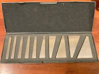
3) Woodpeckers makes a $330 Adjustable Track Square that's used like the clamp-on right angle squares, but has a protractor for angles. Chinese knock-offs are about $70. And TSO has their $470 MTR-18 Triangle that can accurately set 15º, 22.5º, 30º, 45º, and 90º angles (and complements) for direct track saw cutting as well as marking, probably a few other uses, too. But for the "unusual angles" you lose the accuracy. I might play around to see if I can design a completely different adjustable track square that uses the LOC principle for better accuracy for all angles at a far lower cost. Hmmm.
BTW, I did compare my Wixey to my DIN rated square, DIN rated 45º reference, and iGaging 45º bevel. The Wixey measured the 45º reference and iGaging bevel at 45.0º multiple times, but with the 90º square one direction of Wixey arm rotateion gave me 90º but the other direction gave me 90.1º sometimes. It's kind of a pressure thing, too - how hard I press the arms against the reference. Of course, that's not normally how one measures angles, seeking the value you want to get, lol. I'll have to do more to see if it's consistent that one direction of rotation is "better" than the other, or whether it's just slightly different one way and the DRO rounds up/down differently depending on direction, or whatever.
Also, I haven't yet measured the Shinwa against the 90º square. There are two ways I can do this - one is to set the Shinwa at 90º and with backlight look for light gaps when held against the reference. The other is to use the Shinwa to measure the inside of the reference and see what the reading is. The latter is not what the Shinwa is designed for, and with the indicator play, might not be proper.
Finally I know that this kind of precision exploration is not for everyone, and may not even be applicable for almost all woodworking. But, some woodworkers are already spending $300 and up for accurate "normal" angle cutting, so looking at cheaper ways that are more flexible or more accurate seems worthwhile to me.
There are various digital angle "finders" available, but their accuracy is at best +/- 0.1º. Most are worse at +/- 0.2º. For some purposes, that may be accurate enough, but for others, such as making a wide pentagonal frame, even just 1/10º off means there's a full degree of gap in the frame. And while trial and error techniques can enable us to sneak up on accurate angles, or the use homemade guides/templates that are flipped to remove the gap at the price of a small misalignment, there are some projects (tapered boxes is the obvious one), where those techniques can be difficult. Note that the digital inclinometers currently favored by YouTubers also have accuracy of only +/-0.2º - worse than the better finders (protractors).
Before John Economaki retired and sold Bridge City Tool Works to Harvey Tool, he made two versions of an "Angle Master Pro" device that used a caliper to dial in (pun intended) accurate angles. The AMPv2 was reviewed by [member=3513]PaulMarcel[/member] here (blog and video). The AMPv2 sometimes shows up second hand for about $300 or so, but that's rare and even then, expensive.
I was pointed at the Shinwa Sliding Bevel by [member=74278]Packard[/member]. Like the AMPv2, it uses the Law Of Cosines to produce angles based on the length of 3 sides of a triangle. I bought the largest one Shinwa makes on Amazon for about $60. Here's what it looks like:
[attachimg=1]
I don't have an uber-accurate way to measure angles where I'm at right now. For grins, I've been playing around with the Shinwa, a Wixey digital finder, my old AngleWright (also not made, probably accurate to 1/10º at least but not much better), and a DIN-rated square. Here they are nested at 40/50 degree angles (not a good way to test, though):
[attachimg=2]
For $60, the Shinwa seems pretty good for angles between about 20º and 120º (the closer you get to the middle the more accurate it seems to be). But, it seems to be made for carpenters cutting rafters and such - it can be used like a larger, more accurate speed square to guide circular saws cutting 2X lumber.
But, the design using the LOC (Law Of Cosines) has much more accuracy potential. One problem is that, due to the cosine function, the angle markings along one arm are not evenly spaced. This makes obtaining angles like 43.7º difficult since you have to interpolate 7/10 of the way between 43º and 44º. Now, there is a metric scale along the top edge that can help with interpolation (as [member=74278]Packard[/member] pointed out), but an even more accurate procedure would be to use a large caliper from the far end, then do a subtraction to get the effective arm length to plug into the LOC formula. Here's a demonstration of that setup for a 42.77º angle:
[attachimg=3]
Essentially, instead of using the metric scale on the Shinwa, use the depth rod on the caliper to get a more exact reading.
[attachimg=4]
versus
[attachimg=5]
To do this, I had to first measure the Shinwa's two fixed-length arms. This is done between the center of the pivots, since the arms are parallel to the centerline between the two pivots. The fixed middle arm is 330.0mm long, the fixed side arm is 291.0mm (as best I could measure). For the adjustable side there are a couple complications, but not too bad actually. First is that we're measuring not from the pivot but from the far end of the arm. The arm is 640.0mm from pivot to the end (as best I could measure). Second is that Shinwa uses a plastic indicator that slides in a groove along the arm, trapping the pivot and providing an edge against which to line up with the markings. I measured the distance from the edge to the center of the pivot hole at 17.5mm. Thus, the effective length is 640.0 - 17.5 = 622.5 mm.
Now we can use the LOC to get the effective length needed, which we subtract from 622.5 to obtain our caliper reading.
The example in the photos above is for 42.77º. Plug in 291.01 for side a, 330.0 for side b and 42.77 for Gamma (the angle), and side c is 477.91 mm. We subtract that from 622.5 since we're reading from the other end, and you get 144.59mm. Slide the plastic indicator against the caliper depth rod until you get that reading, and viola! you're at 42.77º. Which checks out as far as I can measure, which isn't nearly good enough unfortunately.
In evaluating the Shinwa, the plastic indicator appears to me to be its achilles heel. There's some play in the pivot hole, not quite a mm's worth. When using it to measure an existing angle, you can easily slide the plastic left or right a bit intentionally without changing the arm's angle. That said, with 42.77º needing 477.91mm, a +/- 0.1º (same as the best affordable digital finders) gives you a range from 477.29mm to 478.54mm, which is more than the play I observed. And then factor in that if you just use the indicator without trying to push it, it gives the more nominal/consistent reading (like using a SCMS without trying to push left or right), this already seems better than the digital angle finders.
I don't have a digital printer, but perhaps the next step is 3D printing a new plastic indicator with tighter tolerances.
Compared to the AMPv2, the Shinwa isn't as accurate due both to the play and due to it not being manufactured to high tolerances. Shinwa does a good job and for the money it seems to be good, but the arms aren't lapped for parallelness, nor the holes precision drilled (I didn't observe any play in the pivots though), etc. But, at this large size (60cm size), small differences shouldn't matter much, practically. Since on always has to transfer the angle from the thingie to the cutting tool, there's all sorts of possibilities for introducing error, from bevel alignment against the tool, to the tool itself (like a blade body that isn't perfectly flat or a miter fence that isn't flat or has some play itself, etc.). So we'll never achieve perfection, but I do like trying to eliminate as much potential for error as practical.
Also, the AMPv2 can be used directly to set table saw blade tilt angle, or miter gauge fence / miter saw angles, etc, whereas both the size and configuration of the Shinwa make the blade tilt angle particularly hard to do. You'd end up setting a regular bevel gauge against the Shinwa and then use that against the blade.
What's next here? I see three paths:
1) Design a new plastic indicator in Fusion360 and get it 3D printed.
2) Build my own version of the Shinwa out of aluminum or Delrin. I could build a large one to integrate into a miter sled, as well as a small/medium sized one to set bevel gauges against for blade tilt angles.
3) Woodpeckers makes a $330 Adjustable Track Square that's used like the clamp-on right angle squares, but has a protractor for angles. Chinese knock-offs are about $70. And TSO has their $470 MTR-18 Triangle that can accurately set 15º, 22.5º, 30º, 45º, and 90º angles (and complements) for direct track saw cutting as well as marking, probably a few other uses, too. But for the "unusual angles" you lose the accuracy. I might play around to see if I can design a completely different adjustable track square that uses the LOC principle for better accuracy for all angles at a far lower cost. Hmmm.
BTW, I did compare my Wixey to my DIN rated square, DIN rated 45º reference, and iGaging 45º bevel. The Wixey measured the 45º reference and iGaging bevel at 45.0º multiple times, but with the 90º square one direction of Wixey arm rotateion gave me 90º but the other direction gave me 90.1º sometimes. It's kind of a pressure thing, too - how hard I press the arms against the reference. Of course, that's not normally how one measures angles, seeking the value you want to get, lol. I'll have to do more to see if it's consistent that one direction of rotation is "better" than the other, or whether it's just slightly different one way and the DRO rounds up/down differently depending on direction, or whatever.
Also, I haven't yet measured the Shinwa against the 90º square. There are two ways I can do this - one is to set the Shinwa at 90º and with backlight look for light gaps when held against the reference. The other is to use the Shinwa to measure the inside of the reference and see what the reading is. The latter is not what the Shinwa is designed for, and with the indicator play, might not be proper.
Finally I know that this kind of precision exploration is not for everyone, and may not even be applicable for almost all woodworking. But, some woodworkers are already spending $300 and up for accurate "normal" angle cutting, so looking at cheaper ways that are more flexible or more accurate seems worthwhile to me.