Obtaining Unusual Angles with Precision

The protractor smorgasbord posted is merely a “universal protractor”. The hdv post is a “universal precision protractor”. The vernier scale on the precision model has three times as many divisions. You have to look very closely to find the closest match.

The lower precision model is easier to use because it has longer arms to which to set your (well made) sliding bevel. To use the more precise model you fit a small precision sliding bevel into the open angle on the right.

Then you would sit the sliding bevel on the saw table and adjust the blade to fit the bevel. But if your table has a blade access cover you should assume that surface is not a close enough representation of the table plane to sit the small bevel on so you need to transfer the small bevel angle to a larger (well made) sliding bevel that will sit on the actual table rather than the flimsy insert.

Make a cut and test the resulting bevel. With the test workpiece sitting on a flat surface slide the small precision bevel to it and if there is any light passing between the blade and the wood find the feeler gauge that fits the gap. Then adjust the second sliding bevel to the small one with the feeler gauge in place. You have to move the feeler gauge to the opposite end of the small bevel arm to change the angle of the larger gauge.
 
Very often the lack of precision is overcome by “hand fitting”. 

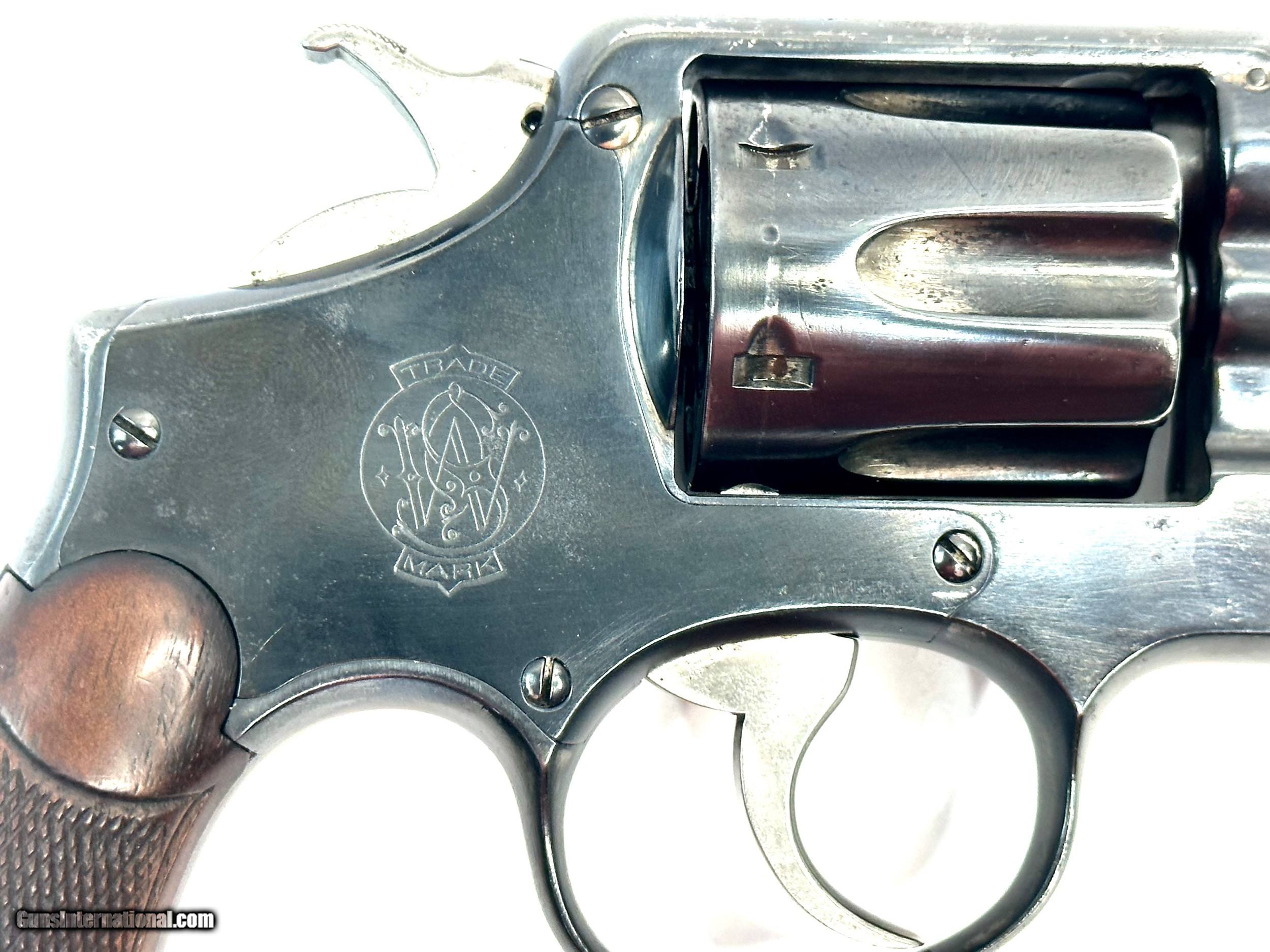
The side plate on a revolver is hand-fitted.  That is the main forging it painted with Prussian blue and the craftsman attempts to put it in place.  The blue will rub off on the high points.  The gunsmith then uses a honing stone to hone off the blue.  Then he repeats this until the side place fits into the forging.  It has been estimated that the fit of the side plate to the forging has no mor than 0.0001” to 0.0002” clearance. (One tenth of a thousandth to two tenths of a thousandth.)

But the exact dimensions are not recorded and are not known. 

You can spot the seam adjacent to the side plate screws.  On some freshly blued guns or stainless guns the seam is not really visible at all. 

I think this happens in woodworking too. A good fit is required and met by the judicious application of a sanding block or file.  I think

Smith-and-Wesson-5-screw-Military-and-police-1st-change-1906-1909_102158956_157594_23626B9A8DEB5DC1.jpeg
 
bobtskutter said:
How do people set their saws to cut these super accurate angles?

Regards
Bob

I do it by making test cuts and assembling.  Make the six sides of a hexagon and glue it up.  Adjust to make tight seams.

This is Starrett’s vernier protractor.  It is $1,000.00.  You would not be able to use this to set the blade angle.  You would have to use it to check the angle on a cut sample.
https://www.starrett.com/details?cat-no=C359FZ

C359FZcUSp1__28581.1714132254.png


And alternate method for “perfect” 45 degree cuts is to “use the opposite sides of the blade”.

If you set your saw to cut a 45 degree angle and it is perfectly set, you will get a 90 degree angle when assembled.

If you set it at 45 degrees and it is actually 45.5 degrees, then the cut on the opposite side of the blade will be 44.5 degrees.  Assembled it will be a perfect 90 degrees. 

This only works with 45 degree angles to equal 90 degrees.  If you remember high school geometry, it was called “complimentary angles”.
 
rmhinden said:
bobtskutter said:
How do people set their saws to cut these super accurate angles?

I am currently making a stand with compound angles.  For this I need tenths of a degree.  Getting reasonable results from a Klein Digital Angle Gauge on the table saw blade, and a Jessem mitre gauge.

Can't argue with what's working for you, but the Klein is accurate only to +/-0.2º when not measuring close to horizontal or vertical.

Michael Kellough said:
The protractor smorgasbord posted is merely a “universal protractor”. The hdv post is a “universal precision protractor”. The vernier scale on the precision model has three times as many divisions. You have to look very closely to find the closest match.

The lower precision model is easier to use because it has longer arms to which to set your (well made) sliding bevel.

Yes, and your point about finding the closest match on the more exact vernier is not to be overlooked. Even on normal verniers, I end up taking a photo, using Photoshop to sharpen, and then zooming in to find what's what. Really slows me down and makes me go "Ugh" every time.

And don't overlook Michael Kellough's point about tablesaw insert plate. One nice thing about the Digital Angle Finders is that by zeroing on the table and then magnetically attaching to the blade, they're easy to use, read, and eliminate a misaligned insert plate from affecting the accuracy (assuming the insert itself doesn't change the trajectory of the stock as its being cut). On the downside, they're harder to use to verify an angle cut in wood.

The BCTW AMPv2 (see above links to Paul Marcel's videos where he uses it in different ways on a project) is sized and setup so that it can directly do blade angles for tablesaw and miter saw, can be used on a crosscut sled to affix a temporary angled fence, and, if all fails, be used to set a bevel gauge that you then use to setup your equipment. For most other devices, including the Shinwa, you use them to set a bevel gauge of the appropriate size and then use the bevel gauge to set up your equipment.

If you're hand cutting, use the bevel to mark the workpiece and cut just outside the line. Then use the bevel to clamp the workpiece in a shooting board and plane to the marked line.

I've previously found when cutting compound angles for things like tapered boxes, that I can't hand fit them because I don't know if the bevel angle is wrong or if the taper angle is wrong or maybe both are wrong. It's just too finicky. Others may be good at that. I don't have problems cutting a board to an accurate thickness or width or length without hand fitting, so I'd like the same for angles other than 90º as well.

 
Packard said:
This is Starrett’s vernier protractor.  It is $1,000.00.  You would not be able to use this to set the blade angle.  You would have to use it to check the angle on a cut sample.
https://www.starrett.com/details?cat-no=C359FZ

It's also graduated to a 1/12º vernier, not much better than Digital Protractors (1/10º) that cost 1/20th of the price and are much easier to set and read.
 
rmhinden said:
bobtskutter said:
How do people set their saws to cut these super accurate angles?

I am currently making a stand with compound angles.  For this I need tenths of a degree.  Getting reasonable results from a Klein Digital Angle Gauge on the table saw blade, and a Jessem mitre gauge.

Bob

I’m not sure I understand what you mean by “compound angles”.  Do the posts on this Craftsman-style porch require “compound angles”?  Can you post an example?

6b23ee3a1a67f9a47671f23dd3cd53b3.jpg
 
Packard said:
I’m not sure I understand what you mean by “compound angles”.  Do the posts on this Craftsman-style porch require “compound angles”?  Can you post an example?

A Compound Angle is a cut in which at least two of the three dimensions are not at right angles.
On a tablesaw, any time you set a blade angle to other than 90 and use a taper jig, or set the blade angle to other than 90 and use a miter gauge not set to 90, you're making a compound cut. On a miter saw, if you set both a miter angle and a blade angle, you're making a compound cut.

When a cut becomes compound, the angles needed are not obvious.

Yes, those tapered porch columns require a compound angle cut. Those columns have 4 sides, but you don't set the blade angle to 45º to achieve a good miter joint, not to 90º to achieve a good butt joint (but you can lay things out for the 90º butt joint and trim off excess afterwards).

Here's a compound cut calculator:https://jansson.us/jcompound.html

 
Yes, tapered columns and tapered boxes are similar simple examples of compound angles.

Somewhere I have a Bridge City Tools booklet giving bevel angles for different degrees of miters and numbers of sides. It’s kinda thick so it probably includes the above for columns/boxes of different lengths as well as numbers of sides.

All of that is surely available online (link posted above by smorgasbord) but can be calculated by people with a better sense of math than me. I have to build the the thing in cad and then find the angle.
 
I made tapered legs from 3/4” stock.  I did not think of the taper as an angle.  I thought of it ad 4” at the top and 2” at the bottom.  So I used a taper jig to cut the taper.

I cut the 45 degree angle as a second operation.

It would be even easier now that I have a track saw.  I would cut the taper with the track and the 45 on the table saw.

I don’t know how easy it is to set the track saw blade at 45 degrees.  If I could achieve an accurate 45, the this would be as simple as a conventional rip.

Getting the correct angles at the top and bottom of the obelisk might challenge me though.
 
Here's a video of a multi-sided tapered table base.

The builder uses a digital angle finder on the blade to set the bevel to 75.3º, and then builds one-off tapering jigs at the desired angle (not showing how those were made).

But at 2:50 in, you can see the pretty large gap, which he hand-planes away.

I'm hoping to avoid that hand-planing step.

 
smorgasbord said:
Here's a video of a multi-sided tapered table base.

The builder uses a digital angle finder on the blade to set the bevel to 75.3º, and then builds one-off tapering jigs at the desired angle (not showing how those were made).

But at 2:50 in, you can see the pretty large gap, which he hand-planes away.

I'm hoping to avoid that hand-planing step.


Hand fitting vs producing to print.

Using a plane, file, spoke shave, etc. is what I call “hand fitting”.  It can result in incredibly tight joints.  But it is not “precision” in the context of measuring accuracy. 

In wood project where appearance is often the overriding factor for precision, hand fitting is a very reasonable approach.

In car manufacturing, they take a hybrid approach.  All the parts have a manufacturing tolerance to comply with, but some aspects of assembly have adjustability built in.

Specifically, door gaps and hood and trunk gaps have adjustable mounting points so that the gaps can be made to be uniform all around.

Using a hand plane for a better fit is, in my opinion, a precision that relates to “hand fitting” and not “working to a measurement”. 

The result may look the same, but the process is different.

Technology will change the process.

When I was a kid, I build a model plane from balsa wood, and tissue paper to cover the structure.  I hand cut all the frame members and spent hours hand fitting.

They also sold kits.  You no longer had to hand cut the frame members, but hand fitting was still required.

They now produce kits that are laser cut.  I would expect greater accuracy to the parts and quite possibly no hand fitting would be required. 

So, my plane (tragically lost in a battle with golfers) and the same plane built from laser cut components might look the same and perform the same, the process would change. 

The hand fitting would overcome the lack of part confirmation to the prints on my hand-made-from-plans version.

Both approaches work.  Precision manufacturing requires more upfront cost for equipment.

Hand fitting requires greater cost in assembly. 

Precision measuring equipment is used to move us away from hand fitting.  So using a hand plane to make corrections falls into the category of “hand fitting”.

 
I wonder how accurate this multi-angle square is.  About $60.00, so it had better be accurate.
 
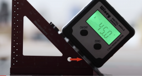
Just saw a segment in a video that demonstrates the problem with the Digital Inclinometers:=CExi3im6p2o2Y_h6&t=97

Here's a couple of screen shots. Notice the gap:
[attachimg=1]

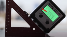
And then a slight blade angle rotation, just enough to increment the display:
[attachimg=2]

BTW, this section of the video talks about intentionally setting the miter this way to keep it tight on the outside when assembled.
 

Attachments

  • Screenshot 2024-04-30 at 10.45.49 AM.png
    Screenshot 2024-04-30 at 10.45.49 AM.png
    1.8 MB · Views: 527
  • Screenshot 2024-04-30 at 10.46.06 AM.png
    Screenshot 2024-04-30 at 10.46.06 AM.png
    1.7 MB · Views: 544
Over cutting (44.9* in this case) has been done forever. I’m guessing thousands of years if not tens of…

Going over an old stair stringer to salvage some wood revealed extreme over cutting, or undercutting since these were pocket cuts instead of through cuts. A 1/4” undercut in a recess that isn’t even 3/4” deep.

[attachimg=1]

I overcut a little on long joints but if the end of the joint will be visible I stick to the true angle then use coarse sandpaper on the long joint to get some relief so the glue won’t push the joint open. Just keep the abrasive away from the visible part of the joint.
 

Attachments

  • IMG_0443.jpeg
    IMG_0443.jpeg
    788.1 KB · Views: 513
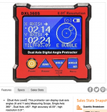
So, I'm less than 3 weeks from returning home, and to my shop. In the meantime, I found this Woot and decided to try it out:https://tools.woot.com/offers/dual-axis-digital-angle-gauge-protractor-2

[attachimg=1]

As you can see, it claims an accuracy of +/- 0.05º, which is far better than the nominal +/-0.2º (sometimes +/-0.1º at horizontal and vertical).  It also has a two-axis rotation mode, which if accurate, might be interesting to see if raising/lowering the blade changes the side to side pitch.
 

Attachments

  • Screenshot 2024-05-13 at 4.59.28 PM.png
    Screenshot 2024-05-13 at 4.59.28 PM.png
    1.3 MB · Views: 479
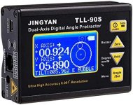
And this, the JINGYAN TLL-90S is the big brother. It costs nearly five times as much but supposedly has ten times higher precision.

[attachimg=1]

But read the reviews.


Attachments

  • IMG_0445.jpeg
    IMG_0445.jpeg
    60.2 KB · Views: 471
Here's a video of a guy testing his Wixey digital inclinometer using a surface plate and sine bar:


The Wixey is basically off 0.1º, which is within spec.

Here's another test using precision triangles, and this time the Wixey is spot on:
 
smorgasbord said:
Here's a video of a guy testing his Wixey digital inclinometer using a surface plate and sine bar:
..
The Wixey is basically off 0.1º, which is within spec.

Here's another test using precision triangles, and this time the Wixey is spot on:
..
Unfortunately those "tests" are just random chance. Claiming a digital scale with a 0.1° resolution to be "spot on" down to 0.1° accuracy is just amateurish at best, misleading at worst. What they actually checked is the Wixie one is indeed within the +/- 0.2° range that it can display. And that even ignores if they used a calibrated reference (most likely not ..).

The thing is, for any digital measure, when one needs accuracy, the scale must have (at least) one digit more of resolution/precision that the accuracy it is to provide - i.e. a 0.01° resolution/precision can convey/provide, at most, a +/- 0.05° of accuracy.

This is unlike with an analog tool, where it is the opposite - the available accuracy can be up to 2x the scale - so a 1°scale can reliably provide up-to 0.5° accuracy, (assuming it is corectly made).

From the TLL-90S specs:
1) High accuracy ± 0.005° and 0.001° high resolution;

That is how a proper metrological spec should look. This one seem to be the real deal.

I would hesitate to buy it through Amazon, though. Better get it from some proper metrological vendor along with a calibration report. Without calibration such tools are 1/2 their value.

ADD:
Michael Kellough said:
And this, the JINGYAN TLL-90S is the big brother. It costs nearly five times as much but supposedly has ten times higher precision.

But read the reviews.
The reviews are kinda as expected. Seems only people who have no insights into metrology "reviewed" it on Amazon .. there is not a single competently written review. So the only feedback from the reviews -> possibly not a good idea to buy this through Amazon (can be shipping damage etc.).

Looked around and found it from a chinese metrology seller:
https://www.alibaba.com/product-detail/JINGYAN-TTL-90S-0-001-Resolution_62254644297.html

That seems a way more sensible purchase path - if one cannot get it with a proper calibration report, there is no sense paying +40% to Amazon and some US reseller for the privilege to get it damaged on shipping ... these folks may even be able to answer a question or two.

One I would have: They state *both* a 0.005° and a 0.5° accuracy on the Alibaba listing. So which one is it ? Is one for the laser, other for physical, or maybe 0.5° is just for the display ? .. metrology gets complicated fast ..
 
Back
Top