Octagon

Birdhunter

Member
Joined
Jun 16, 2012
Messages
4,144
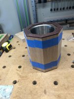
I'm trying to get set up to make a series if 8 sided cylinders each to hold a wine chiller. The sides are 3/4" thick, 8" high, and about 3.5" across.

Ive done 2 prototypes and one "real" version. My problem is getting the bevel angle perfect to eliminate and gaps. I use an electronic angle gauge to set the SawStop blade at 22.5 degrees. Of course, any error is multiple 8 times.

I will end up building 8-10 of these items as Christmas presents.

Anyone with a solution?
 
Digital gauges are only accurate if your saw is PERFECTLY level, and then they're still marginal.

Do you have a bevel gauge? You could bisect a square angle twice on a piece of paper and use that to set your bevel gauge, if you don't have anything else to give you an accurate 22-1/2.

Another trick I've seen is to get the 22-1/2s as close as you can, assemble in two sections of 4 pieces each, run the sub-assemblies across a jointer and then put the two halves together.
 
Since the Sawstop tilts away from the fence it should be easier than with my old Walker Turner.

Cut all the stock a little (or a lot) oversized with the bevel as close to 22.5* as you can.

Dry assemble eight pieces with a a pair of band clamps and check the joints.
Might need to tape them together first.

Measure the gap with a feeler gauge. You know that represents 8 times the amount you need to adjust.

Set a stop on whichever side to the saw blade the blade needs to move away from.
The stop should touch the tooth of the blade before the blade is moved. Mark that exact tooth with a Sharpie so you always use it for reference.
Move the blade away from the stop then place the 1/8th whatever feeler leaf on the stop and bring the blade back to touch the feeler leaf.

Recut and check the assembly again. If you need more fine tuning at this point you should be able to get it by simply putting layers of tape on the saw table either close to the blade or close to the fence.

Another alternative is to add an auxiliary angle indicator to the arbor assembly. Make it at least a foot long (longer the better) hanging straight down when the bevel is already in the ballpark so gravity will have less influence. At that distance from the pivot point a degree will be nearly 1/4” wide so you can stick a Post It note on the cabinet and mark the positions you try until the bevel is perfect.
 
Can you please post a picture of your prototypes it would help me to understand what your trying to accomplish.  I'm planning on a large octagon for a poker table rail but was planning on cutting 22.5 with a miter gauge vs. tilting the blade.

Thanks,
Rich
 
Rich Kline said:
Can you please post a picture of your prototypes it would help me to understand what your trying to accomplish.  I'm planning on a large octagon for a poker table rail but was planning on cutting 22.5 with a miter gauge vs. tilting the blade.

Thanks,
Rich

I’d make a jig for the MFT to do that. Easier, more repeatable, and safer. A vernier protractor and a couple of straight edges would get you close then you could use similar methods to what I posted above to close the gap. A digital bevel gauge @ .1* resolution is too coarse for segments large enough to make a table, but if you can afford to do more cutting and adjustment it can work.

Put the point of the pie slice toward the front of the MFT. Use an adjustable stop on the base of the triangle to set the size. Start off farther out from the final size to allow for adjustment.
 
I cut all the pieces square edged about 1/64 over width. Then I swing the blade to 22.5 and cut some test pieces 2 to 2.5" thick with the mitre gauge. I tend to leave the toe a wee bit long. 

Then I mount a sacrificial piece on the fence mounted high the thickness of the parts minus 1/8".
I use a piece of the material to scribe a line on the sacrificial fence. Then adjust the fence so when you raise the running blade into the sacrificial piece it cuts in on and below your mark. I tend to set it so it leaves just a whisker so as not to alter the width. Having the sacrificial piece off the table gives a space  for the cutoff so you don't get kickbacks on the cutoff.

Jeff said;
"Another trick I've seen is to get the 22-1/2s as close as you can, assemble in two sections of 4 pieces each, run the sub-assemblies across a jointer and then put the two halves together. "

I do this also it makes the glue up easy.

 
Picture


Attachments

  • D66F7C2B-1BC0-4AC8-BE15-802FAC6A4D54.jpeg
    D66F7C2B-1BC0-4AC8-BE15-802FAC6A4D54.jpeg
    346.7 KB · Views: 362
  • D66F7C2B-1BC0-4AC8-BE15-802FAC6A4D54.jpeg
    D66F7C2B-1BC0-4AC8-BE15-802FAC6A4D54.jpeg
    346.7 KB · Views: 309
Assuming that your angle settings are pretty close, but off just enough to give a slight gap at some joint(s).

The fix is pretty quick and easy - glue the part up as two halves, leaving two opposing joints unglued, this will let you clamp it as an assembly as shown. Then take your two halves to the jointer and take a light skim cut across the width, you can check by laying a straightedge across the part. Once you have skimmed both halves, go ahead and glue up the final assembly. If the initial angle is very close, you're only going to take a skim across the high tip (either on the outside or inside), not enough to be noticeable, although you can also take a quick pass with a hand plane to correct it.
 
"Digital gauges are only accurate if your saw is PERFECTLY level, and then they're still marginal."

I don't believe that is true for all makes. On some you can zero out to the reference surface, in the case of a TS to the table. Then when you take a reading on the blade it is referenced to the table not to true level or plumb.
 
Depending on how picky you choose to be with the final sanding of the outside corners you could choose to just burnish the corners closed if the openings are small / hairline. Just take a polished steel rod (like a burnishing tool for hand scrapers) and run it down the corner seam crushing the wood fibers together. It will create a mating corner that, after sanding will be oh so slightly rounder over but it should effectively close most small gaps. It just depends on how crisp you want the outside profile to be. Obviously it also depends on the success of your next attempts to dial in your process.

Also in looking at your picture it looks like once assembled the inside might not show. If that is true you can slightly undercut the last joint and just touch up that last leading edge to mate up. If it’s a bit open on the inside it does not look like it will show. It just has to be close enough on the inside for the glue to make a solid bond.
 
A number of excellent ideas here and I’ll try them.

I tried adding the top and bottom  trim pieces on before I cut the bevels. Is there a better technique?
 
Good question about the trim. You certainly could try mounting it after the staves are glued up but I’m not sure that you won’t just be trading one difficulty into two. You would end up with two challenging set ups instead of one but it would make the stave glue up a little more forgiving. It will also be easier to tweak the last trim piece to fit (as opposed to the last stave).  Tough call.
 
With the trim applied to the staves, the jointer method is going to have problems...unless you cut in a couple inches, turn around and come from the other direction.
 
Just how much does the inside matter?
Seems to be some people just making hard work out of this.

Cut it ever so slightly more acute than it needs, tape the outsides and the glue sorts the rest.
 
I’d assemble the staves, then trim the top and bottom. The bevel rip is much harder to get right than the trim miters.

Tom
 
Back
Top