Part 1: Routing/Milling 80/20 for Festool clamps using an MFS & a 1010

Cheese

Member
Joined
Jan 16, 2015
Messages
12,503
I have a work bench extension table that's made from 40 series 80/20. I'm also in the process of refinishing a Simpson full view exterior door that I need to enlarge the hinge mortises on. I decided the hinge mortising would be easiest to perform at waist level using the MFS.

Thus, to enable the door to be secured to the table horizontally, on its edge, I needed to remove 2 of the 80/20 legs and route in clearance slots to receive both Festool Quick clamps and a couple of 5/16-18 carriage bolts on "L" handles that attach some angle supports to hold the door.

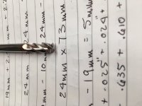
I decided to use a 1/4" diameter, 4-flute carbide end mill with a 10.8 mm router bushing on the 1010 router. This combination gave me an offset of 2.2 mm per side.
The Festool clamp leg measures .470" wide by 3.750" long.  I converted these numbers to metric and then added the offset of 2.2 mm to each side.
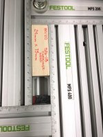
Thus the Festool clamps need a clearance slot 16.5 mm wide by 100 mm long. However, because the 4-flute bit is not a plunge bit, I wanted the MFS to overhang the front of the 80/20 by 10 mm. So I added another 10 mm to the length dimension.
I set the MFS to 16.5 mm x 110 mm and I set the speed of the router to 3.

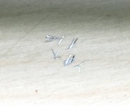
The 4-flute carbide end mill

[attachimg=1]

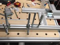
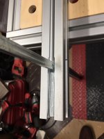
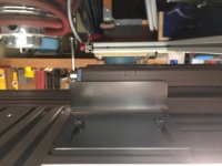
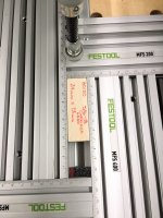
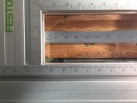
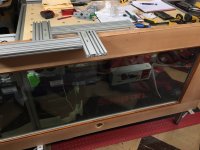
The basic setup showing clamping methods and the MFS assembled and upside down.
[attachimg=2]

[attachimg=3]

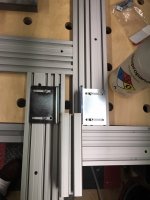
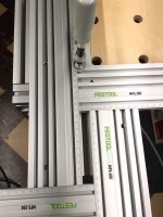
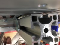
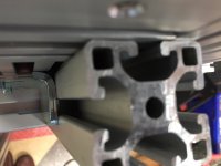
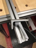
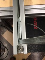
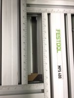
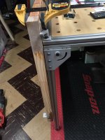
The MFS is placed over the 80/20 and clamped in place. Notice that it overhangs the 80/20 by 10 mm so that there is clearance for the end mill.
[attachimg=4]

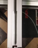
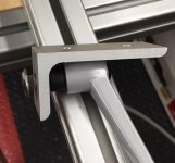
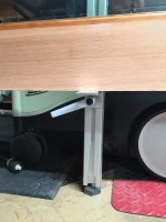
This is the finished clearance slot and the next photo shows the Festool clamp installed.
[attachimg=5]

[attachimg=6]
 

Attachments

  • 6564.JPG
    6564.JPG
    596.5 KB · Views: 3,294
  • 6565.jpg
    6565.jpg
    719.2 KB · Views: 4,476
  • 6566.jpg
    6566.jpg
    736.4 KB · Views: 3,324
  • 6571.jpg
    6571.jpg
    759.1 KB · Views: 3,315
  • 6579.jpg
    6579.jpg
    742.2 KB · Views: 3,283
  • 6582.jpg
    6582.jpg
    659.2 KB · Views: 3,324
One of the things that works out well when using the MFS with 80/20 extrusions, is that the extrusions are slightly narrower (by design) in the slot area. So if it's a 40 mm square extrusion, the slot area will measure 39.6 mm. This means that once the MFS brackets are snugged up on the MFS, the MFS cannot be placed over the extrusion. Rather it has to be slid on the extrusion from the front. This makes the connection between these 2 items more secure. A single clamp on the top of the MFS secures everything.

This shows the MFS clamp on the 80/20 from underneath.

[attachimg=1]

This shows the clamp and the 80/20 in contact with one another.
[attachimg=2]

This shows how little the 80/20 can move away from the MFS clamp. That sliver of light is maybe 2 mm. You can also check the distance on the bottom of the bracket vs the slot...again, maybe 2 mm of movement.
This makes the machining of the 80/20 fast. Slide the MFS off, rotate the 80/20 to machine a different side, slide the MFS back on and clamp with a single clamp.

[attachimg=3]
 

Attachments

  • 6570.jpg
    6570.jpg
    722.4 KB · Views: 3,302
  • 6569.jpg
    6569.jpg
    642.5 KB · Views: 3,252
  • 6567.JPG
    6567.JPG
    768.1 KB · Views: 3,205
As I mentioned in Part 1, I also needed to slot the 80/20 to fit the head of a 5/16-18 carriage head bolt. I'll spare you the math and just say that it needs a 24 mm x 24 mm slot. Heres a shot of the bolt/handle assembly.
[attachimg=1]

I opened the MFS to 24 mm wide but kept the length to the original 110 mm. I decided to use a wooden stop block in the MFS to limit the router travel to 24 mm. I again wanted to maintain a 10 mm gap for end mill clearance at the front of the 80/20 extrusion. [attachimg=2]

I determined I needed to cut a stop block that was 24 mm x 73 mm.
[attachimg=3]

Using the same end mill and router bushing and inserting the stop block produced this.
[attachimg=4]

[attachimg=5]

Final product for using both clamping elements.
[attachimg=6]

[attachimg=7]
 

Attachments

  • 6597.jpg
    6597.jpg
    237.3 KB · Views: 3,905
  • 6596.JPG
    6596.JPG
    865.8 KB · Views: 3,189
  • 6595.jpg
    6595.jpg
    367.4 KB · Views: 3,142
  • 6594.jpg
    6594.jpg
    344.8 KB · Views: 3,190
  • 6593.JPG
    6593.JPG
    956.1 KB · Views: 3,293
  • 6591.JPG
    6591.JPG
    717.4 KB · Views: 3,188
  • 6584.jpg
    6584.jpg
    82.2 KB · Views: 3,180
Michael Kellough said:
Very nice results!

Thanks Michael [smile]

FWIW...I use isopropyl alcohol as a lubricant. It gives a nice clean cut and isn't as messy as WD40. Besides it evaporates.  [cool]
 
Cheese said:
Michael Kellough said:
Very nice results!

Thanks Michael [smile]

FWIW...I use isopropyl alcohol as a lubricant. It gives a nice clean cut and isn't as messy as WD40. Besides it evaporates.  [cool]

Never thought of using alcohol. The latest addition to my prop kit is a small spray bottle of alcohol from CVS. Very handy and now it will get more use.
 
Michael Kellough said:
Never thought of using alcohol. The latest addition to my prop kit is a small spray bottle of alcohol from CVS. Very handy and now it will get more use.

Just be careful Michael, nonferrous metals only as it is flammable. And you don't need much. It evaporates fairly slow so a little squirt will last for 20-30 seconds. The upside though is it drys clean.

Sometimes when drilling holes in aluminum, some of the aluminum will weld itself to the drill bit. Rather than removing the drill bit and manual scraping the aluminum off (that stuff is on there), I'll give it a squirt of IPA and between the heat, the vibration and the alcohol, the aluminum shard will remove itself from the drill bit.  [cool]
 
Cheese said:
I'll give it a squirt of IPA and between the heat, the vibration and the alcohol, the aluminum shard will remove itself from the drill bit.  [cool]

[member=44099]Cheese[/member] seems like a terrible waste of India Pale Ale to me although I much prefer a good stout or porter  [big grin]

Ron
 
A very nice illustration and description of a process many 8020 users could apply to their benefit.
One question: It seems the issue of the end mill not being bottom cutting would be mitigated by just plunging the router centered over the slot. This would be useful if one wanted to do the routing without disassembling.
 
rvieceli said:
Cheese said:
I'll give it a squirt of IPA and between the heat, the vibration and the alcohol, the aluminum shard will remove itself from the drill bit.  [cool]

[member=44099]Cheese[/member] seems like a terrible waste of India Pale Ale to me although I much prefer a good stout or porter  [big grin]

Ron

Ya Ron, as I typed that out I had mixed emotions about using the term IPA.  [big grin]

But then I figured heck, if you want to squander your IPA on machining some aluminum...you’re a better man than me...or maybe just less thirsty.  [smile]
 
greg mann said:
A very nice illustration and description of a process many 8020 users could apply to their benefit.
One question: It seems the issue of the end mill not being bottom cutting would be mitigated by just plunging the router centered over the slot. This would be useful if one wanted to do the routing without disassembling.

Thanks Greg...to your question, that’s the reason I decided to start the routing 10 mm from the end of the 80/20. That gives a nice pocket in which to plunge the router bit and not engage it in the aluminum. A sort of dead zone. Then moving in a clockwise fashion, you’d only be removing a small amount of material. Which brings up a more important point that you’re alluding to.

My real focus in this “how to tutorial” was to provide a “you can do this” moment...I still hate that commercial.  [eek]

With more people using 80/20, this seemed like a useful discussion in how to optimize the functionality of using 80/20 materials. If you’re using 80/20 then you’re also using the slots for clamping. However, butt up 2 pieces of 80/20 material to each other and you lose the access to at least one of the clamping slots.

Another barrier to knock down is that it seems that a lot of people are intimidated by trying to rout aluminum. I consider it to be just another more dense version of wood. Unfortunately, when using a handheld router on aluminum, the sounds are different as well as the tactile feel through the router. There is a cacophony of different sensations that are both new to and disconcerting to the person that may be well versed in using a router on hard wood.

Just my minimal effort in encouraging woodworkers to try something different.
 
Are there any negative effects of sending aluminum chips through the router and CT hose during machining?
 
Cheese...great “how to” share ...so much more cleaner/precise than my wooden jigs
Thx for the IPA tip and nice pictures!
 
DynaGlide said:
Are there any negative effects of sending aluminum chips through the router and CT hose during machining?

Not that I'm aware of because they really aren't hot and they're also very small. They come off the end mill as a series of very fine slivers.

Besides, it's best to use some type cutting fluid and whether it's AlumaTap, WD40 or IPA, the small chips kind of form a rough slurry and just don't get sucked up for the most part. I'd be surprised if aluminum chip evacuation is any more than 10%-20%.

Here's a photo of the aluminum chips. The photo can be misleading, these little shards are about .005"-.007" thick.

[attachimg=1]
 

Attachments

  • 6624.jpg
    6624.jpg
    347.9 KB · Views: 2,951
Vondawg said:
Cheese...great “how to” share ...so much more cleaner/precise than my wooden jigs
Thx for the IPA tip and nice pictures!

Thanks Vondawg... [smile]  the MFS has been a game changer for me. Like everyone else, I've had to make routing guides/jigs for most of my adult life and maintaining accuracy has always been an issue. Then having put so much time and labor into these guides I can't stand parting with them. So they get saved in a corner of the shop JUST IN CASE I EVER NEED IT AGAIN. [crying]  [crying]

With the MFS I just keep a notebook with the settings used and whatever other pertinent information I need. Pretty simple.
 
Routed lock cutout into Kawneer aluminum door, 1/4" Amana aluminum routing bit from Toolstoday, lubed with WD-40 in hand spray bottle.  Saved a $700.00 prep charge.
View attachment 1
 

Attachments

  • IMG_20170627_100327051.jpg
    IMG_20170627_100327051.jpg
    3.4 MB · Views: 457
This is the final part in this series. As mentioned in Part 1 this entire exercise was because I needed to hold an exterior door to my workbench.

The lower "L" bracket in place to support the edge of the door.
[attachimg=1]

The lower "L" bracket and the upper "L" bracket in place while the door is clamped to the upper "L".
[attachimg=2]

This general door position makes enlarging the existing hinge mortises easy. Everything is done from above and it's all at waist level.
[attachimg=3]

Of general interest, I'm a huge fan of Starrett flexible machinist scales. I have both 6" and 12" versions and use them constantly for precision measuring. On some projects I'll use them more than a tape measure.

Here's a shot of me placing the edge of the existing hinge mortise 3.5 mm from the MFS. This measurement is being done inside a small pocket, an impossible task with a tape.

[attachimg=4]

The reason this works well is because the Starrett scales are so flexible. In the final photo notice how much the scale is flexing. I've owned these scales for 45 years and have done this type of measurement with them for 45 years. A testament to their robustness.  [big grin] [big grin] [big grin]
[attachimg=5]
 

Attachments

  • 6617.jpg
    6617.jpg
    286.9 KB · Views: 2,915
  • 6616.jpg
    6616.jpg
    275 KB · Views: 2,910
  • 6621.JPG
    6621.JPG
    1,007.3 KB · Views: 2,974
  • 6620.JPG
    6620.JPG
    918.9 KB · Views: 2,998
  • 6619.JPG
    6619.JPG
    870.4 KB · Views: 2,990
[member=44099]Cheese[/member] great tutorial. I need to cut some slots in my assembled sys/mft cart on the front face. Since I cannot enter the slot from the end and will need to plunge I'm thinking of using an 8mm or 1/4" bit that'll fit the 15 series slot.

Assume you are cutting full depth in one pass, just letting the mill side-cut & shave from the slots edge?

It's gonna be fun cutting in a horizontal orientation...

Thanks,

RMW

PS - grab a few of these and you can use your L-brackets in slots without the carriage bolt clearance:

[attachimg=1]


Attachments

  • ScreenClip.png
    ScreenClip.png
    82.4 KB · Views: 2,865
Richard/RMW said:
[member=44099]Cheese[/member] great tutorial. I need to cut some slots in my assembled sys/mft cart on the front face. Since I cannot enter the slot from the end and will need to plunge I'm thinking of using an 8mm or 1/4" bit that'll fit the 15 series slot.

1. Assume you are cutting full depth in one pass, just letting the mill side-cut & shave from the slots edge?

2. It's gonna be fun cutting in a horizontal orientation...

3. PS - grab a few of these and you can use your L-brackets in slots without the carriage bolt clearance:

Thanks Richard  [smile]

1. Full depth, one pass. Produces nice little shards. Make sure you don't climb cut.  [eek]  Climb cutting on a knee mill is one thing, climb cutting with a handheld router is another. CW direction. [member=25351]rst[/member]  has mentioned that he uses and likes a Whiteside aluminum bit. That may be in my future.

2. I hear you...better you than me. [big grin]

3. Thanks for that Richard, I forgot about those because I've never used them before. I'm placing an 80/20 order today so I'll add a couple to the order.
 
Richard I know you don’t want disassemble the cart but maybe pull the systainers and flop it over on the back or side. I am really uncomfortable with out of position free hand routing.  [eek]

Ron
 
Back
Top