Plunge Router Inaccuracy?

The depth stop/turret on the Bosch floats on a spring too Bob so that the click positioning can work - when setting a cut depth it definitely needs to be well pushed down to bottom it out. This mind you if the sloppy posts/offset stop theory stands up may worsen any tendency for the body to tilt upon contact with it.
I'm definitely not ponying up for a 1400 without (a) confirming what is happening with the Bosch and that it's not fixable and (b) checking the a 1400 or larger Festool router very carefully.
The fine finishing cut idea and more are worth running a few more tests to try out Bill/WF.
Something is definitely happening to permit the plunge to go deeper and the cutter to tilt than the nominal depth setting when it's unlocked. I tried to remove the plunge marks by pushing down harder on the stop and taking another pass (a situation quite similar to the fine finishing cut scenario) while doing the job but no matter what I did it would not do so. It just produced more plunge marks..
In terms of minimising the problem I suspect you're right that it's probably best not to push down too hard when plunging. I'm thinking also that it might help to rework the depth stop by removing the spring/fitting a weaker one, and to partially do up the plunge lock before plunging. (the last so that it's providing some stablilisation but not producing so much friction that you can't easily overcome it)
The fit/tolerance of the guide posts in the bushings and their length of engagement must presumably be the underlying factors in this situation.
I tried to find a parts drawing for the Festool 1400 but had no luck. They talk of it locking on both posts to minimise (notably not eliminate) tilt which probably won't help much while plunging - but on the other hand they also talk of the posts being ground to tight tolerances. A bulge in the housing might or might not (?) suggest a good long guide bushes.

A PS added after posting. The parts drawing for the Bosch doesn't show the bushes separately (could it be that the posts are run directly in the aluminium plunge body?) Whatever the case the engagement is very short - more or less a necessity given that the plunge base on the GMF 1400 is removable so that it can be substituted with a fixed base.
It all seems a bit daft unless I'm missing something - why would precision plunge router need a fixed base anyway? The Festool doesn't seem to use one for example...
 
Blackerty said:
It all seems a bit daft unless I'm missing something - why would precision plunge router need a fixed base anyway? The Festool doesn't seem to use one for example...

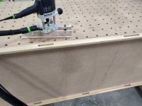
Winged bits.  It's easier to micro adjust the height using the fixed base.  I find that to be one of the annoying bits with the festool routers TBH since you have to unplunge, micro, then plunge again.
 
Height adjustment turrets that have the spring washer under the turret have always bugged me. The spring washer should be above the turret and the rotating turret base should sit solidly on top of the router vase.
 
Blackerty said:
I tried to remove the plunge marks by pushing down harder on the stop and taking another pass (a situation quite similar to the fine finishing cut scenario) while doing the job but no matter what I did it would not do so. It just produced more plunge marks..
In terms of minimising the problem I suspect you're right that it's probably best not to push down too hard when plunging. I'm thinking also that it might help to rework the depth stop by removing the spring/fitting a weaker one, and to partially do up the plunge lock before plunging. (the last so that it's providing some stablilisation but not producing so much friction that you can't easily overcome it)

Have you considered to lift the router a little out, lock the plunge, turn the router on and then lower the router to its working position before doing the final pass? That way you will not operate the plunging while the router is cutting.

To get more control over the lowering, you could put 0.5 mm cardboard under the router while doing these initial steps and then just start routing, sliding the router off the cardboard and then remove the cardboard before returning to that spot.
 
Are you guys all forgetting the micro adjust? That little thumbwheel (green) at the base of the depth rod will add or subtract .1mm per click. All you have to do is set your exact depth, click up a couple of tenths of a millimeter and go at it in your usual way. Then click back down for a final clean-up pass.
One of those Festool advantages. The OF1010 does it too, I assume the OF2200 does also?
 
Thanks A. The shim is a good idea. It'd take some figuring out to get it working but something like a self adhesive plastic film attached to the base which would peel off for the final pass might do the trick.
Lowering while locked is a bit more difficult unless you have a fix. The two fences in my case might with a lot of care make it possible without damaging the edge of the slot, but at 39mm depth of cut it wouldn't take much of a tilt error to do harm.
It turns out (see my next post) that there are engineering reasons why the Bosch plunge mechanism is not very precise, and why some of these problems are unpredictable.
 
The edge mortising attachment might serve you well to control the side to side motion. There may be an advantage to making one yourself though, depending on the size of the parts you need to cut into.
Mine is self made, uses the regular extractor attachment and does a pretty good job.
 

Attachments

  • Feature wall fill slots.jpg
    Feature wall fill slots.jpg
    318.4 KB · Views: 167
So please pardon another post but the discussion got me going  [unsure]
I've just finished stripping and measuring the plunge mechanism on the Bosch GMF 1400CE.
Put politely - it's not exactly a precision device.
The big question is how the Festool product might compare.
The plunge raises and lowers on two posts, but only one of these at 15.6mm dia (which has some sort of slip coating on it) runs in a bronze bushing which is 36mm long.
The plunge lock couldn't be much simpler - it's just a bronze screw which when tightened by turning the locking lever screws down directly on to this post.
The second post of 12mm dia is steel and passes through an elongated hole in the aluminium (?) plunge casting - this has a clearance of probably approaching 0.4mm. i.e. the casting doesn't contact the post. There is no bushing on that side, only a hard-ish rubber 'O' ring in a seat above this hole which runs on the post.
The router is therefore cantilevered from the first/main post with the bushing.
The second post and 'O' ring are probably there mostly just to prevent rotation of the motor assembly around the main post. It's hard to know exactly how much the 'O' ring might compress, but it deflects by a visually obvious several tenths mm under sideways finger pressure on the post. About 50% of whatever does occur will translate into a horizontal movement of the cutter.
The fit of the critical first/main post in the bronze bushing is loose - the clearance (difference in diameter between the bore of the bush and the post) measures of the order of 0.14mm. (0.0055in or 5 1/2 thou)
To put this in perspective - a class 3 medium sliding fit (a not especially precise one which is loose enough to run up to 600rpm, but which will deliver detectable wobble in a short bushing) from the fit tables for a 15.6mm dia shaft entails a clearance of between 0.015 and 0.061mm.(0.0006 to 0.0024in)
That's between x2 and x9 times less clearance than seems to be present on the above main post.
A really precisely located sliding fit (not practical in an application like this) could be even tighter.
The 0.14mm clearance of the first post in the 36mm length of the bushing by calculation translates to roughly 0.22 deg of tilt. The cutter overhang (from the main post to the centreline) is of the order of 60mm, the tilt angle over this distance consequently translates to something of the order of 0.2mm of a height change for the cutter.
That alone is more than enough to produce marking under the end of the cutter and to the sides of a groove, but checking the motor unit found that there in addition was very detectable but unmeasured slop (enough to produce a very audible clunk) in the top bearing. The bottom/cutter end bearing was tight and there was no detectable end float.
Putting it all together there's at minimum four sources of tilt/cutter movement in there - the slop in the bronze bush on the main post, whatever deflection occurs in the 'O' ring on the other post and whatever tilt the clearance in the motor top bearing permits.
It seems likely given that tightening the plunge lock got rid of a lot of the unwanted cutter movement that the slop in the bushing on the main plunge post was a significant issue in my situation.
The fourth is the likelihood that the structure in hanging from a single well overhung 15.6mm dia post mounted in a heavily hollowed out and likely quite flexible base casting (the bases on the Festool routers look notably thick in the pics) deflects significantly under its own weight and the various feed forces. This will happen even if the plunge is locked. It wouldn't in this situation be difficult to pick up another few tenths mm movement...
The plunge stop turret was mentioned as a secondary matter. It turns out that the detent uses a spring loaded round headed pin engaging in dimples in the bottom of the turret which doesn't seem to disassemble. (it could be pressed in)
Most of the lift/slop in mine turned out to be down to the central retaining screw not having been properly tightened during manufacture. This wasn't the cause of my cutting issues  - the plunge as described before was pushed down hard enough in use to deliver repeatable stop heights....
 
Crazyraceguy said:
Are you guys all forgetting the micro adjust? That little thumbwheel (green) at the base of the depth rod will add or subtract .1mm per click. All you have to do is set your exact depth, click up a couple of tenths of a millimeter and go at it in your usual way. Then click back down for a final clean-up pass.
One of those Festool advantages. The OF1010 does it too, I assume the OF2200 does also?

Absolutely it does, and it's incredibly rigid in use, zero slop. When I did panel work, I'd have to leave the router setup to not lose the exact setting. With the micro adjust it's so easy to repeat settings exactly. The height locking on the OF2200 is also the best I've used.

CRG, you've just gotta get one mate! ;-)
 
FWIW... if this was my itch to scratch I'd do what I needed to do to accomplish the task and then just come in with a final finish pass. Just a kiss and a promise.  [smile] The task would be completed and my neurosis would be soothed.  [big grin]
 
If a lot of your cutting is larger stuff I would suggest going right to the OF2200. I've definitely ran into cases where a tool was too small or not powerful enough. I'm sure the OF1400 is nice (I don't own one yet), but it's not in the same league for larger cuts vs the OF2200. Much more rare to have a tool be too large or powerful.

 
Crazyraceguy said:
smorgasbord said:
Any side to side differences are from how to constrict the router via fences/guides/bushings, not in the quality of the router itself.

I'm not so sure about that, there is definitely a difference routers. ...

I think you're misunderstanding me. I'm talking side to side differences, as in left to right, not up/down via plunge.

Although I will admit that if the plunge isn't perfectly vertical, then you will get some cutting width differences no matter how good your fixturing is.

That said it seems many of us have pointed that doing a final "clean up" pass at the end is good practice no matter how good/bad your router is.
 
Blackerty said:
Lowering while locked is a bit more difficult unless you have a fix.
That is why I suggested using 0.5 mm cardboard as a shim. You don't glue it to your router base. You glue it to the wood surface it is sliding on. And you only do that at the starting position.

Then you put the router on the cardboard, plunge it and start routing. When the router slides off the cardboard covered part, it is lowered 0.5 mm in a very controlled action, only tipping a very little because of that 0.5 mm step. Then, when the router is free of the cardboard, you remove the cardboard and go back over the spot where the cardboard was so you get everything routed at final depth.

If the 0.5 mm step is too much tipping, you can build a ramp of different thicknesses of cardboard along the track. Or you could just use tape strips of different length on top of each other. The Tesa blue tape is around 0.1-0.15 mm, so 4 layers at the start position, stepping down to 3-2-1-0 layers along the track wold create very little tipping.
 
smorgasbord said:
I think you're misunderstanding me. I'm talking side to side differences, as in left to right, not up/down via plunge.

Although I will admit that if the plunge isn't perfectly vertical, then you will get some cutting width differences no matter how good your fixturing is.

That said it seems many of us have pointed that doing a final "clean up" pass at the end is good practice no matter how good/bad your router is.

Yeah, I was assuming that you were referring to jagged edges, from a router that doesn't plunge nicely or allows the bit to wobble around at different depths as you work your way down.
 
Thanks for the explanation A. It'd take a little care with a long cutter to avoid accidentally tipping sideways to mar the side of a slot but a tight plunge mechanism in combination with for example the two fence set up I used should make your fix possible. It sounds workable as a way to avoid the circular dimples at plunge points that seem to be more or less universal.
The difficulty beyond that is that a poorly located plunge can greatly deepen these dimples and cause the rather more serious damage to the sides of the slot seen in the pics i posted.
There's quite a lot of data to take in. The result may be that the implications of my post with measurements etc above which identifies causes of the lack of precision in the Bosch plunge may not stand out.
My example contains at least four sources of unwanted cutter movement. Each of these alone is enough to produce a significant problem. They combined judging by my experience to cause the unwanted tilting, raising and lowering and sideways movement of the cutter demonstrated in the pics.
This to my mind makes this router unusable for deep plunge work where finish and accuracy matter.
I'm trying to dig up hard information regarding the engineering of the Festool routers but not having much luck. Does anybody know where parts drawings can be accessed on line?
 
Blackerty said:
I'm trying to dig up hard information regarding the engineering of the Festool routers but not having much luck. Does anybody know where parts drawings can be accessed on line?

If you're want to find the actual drawings with dimensions, good luck on that. That's a proprietary issue and Festool wouldn't release those details.
If you just want a general assembly drawing to show how the router is assembled look it up on ekat.
https://ekat.festool.de/login2/app?...29351DB45EA618EEFB7B1BB136D42B8044FCE28E6056D
 
Thank you C.
I'm unfamiliar with Festool world.
It's asking for a log in and there seems to be no way to get behind that page .
Does it require being a Festool owner or am i missing something?
 
Blackerty said:
Thank you C.
I'm unfamiliar with Festool world.
It's asking for a log in and there seems to be no way to get behind that page .
Does it require being a Festool owner or am i missing something?

The link has probably expired.

Go to the top of this page and under Festool Websites click on:

Festool USA
Customer Service
Spare Parts Catalog
Routing
Routers
and then choose one.
 
Thanks C.
That route got me as far the link to open the spares catalogue (EKAT) but it doesn't open - just sits there with a blank page displaying the name of the page in the browser. Same for the UK.
There's no equivalent link on the German site.
The Festool Ireland spares page eventually opened (no doubt because I'm in Ireland) but with prominent bureaucratic waffle to the effect that EU law (????) demands that all repairs are carried out by a competent or whatever person which they in effect deem to be their local subsidiary.
It then opens to only an exploded drawing showing numbered parts - not even a list with descriptions of the items.
It's not even clear that you can buy parts to do your own repairs...
Smells like yet another corporate use of the power of IT platforms and as has become he norm here in the EU the usual laws to suit their interest - all designed to force the punter to use their preferred and no doubt very expensive parts and service channels....
A guess suggests that the German distributors and local service providers wouldn't wear a similar move there.
I could be persuaded to rise to the price for a top quality tool that delivers otherwise unavailable capability, but that's a serious downside  - I'm on principle unlikely to submit to that sort of diktat.
There's been a fortunately only partially effective attempt to force similar in respect of domestic electrical repairs here. It's great fun - most of the time the 'expert' with the bit of paper is a clueless but entitled kid that knows less than you do....
 
While we may have it easier to find things on the EKat pages here in the US, you can't order directly from it, which seems like a giant missed opportunity to me.
You still need to find a dealer who is willing/able to order them.

The dumb thing that happens here is that we are restricted as to availability of many products.
 
Back
Top