Power and hand together: Building a pair of nightstands

derekcohen

Member
Joined
Jun 22, 2008
Messages
922
The first 9 chapters of this build are on my website (bottom of this Index Page:http://www.inthewoodshop.com/Furniture/index.html ). Read these for the full background to the build. This features a mitred case with a curved front, and two drawers. One is a main drawer with curved front and slipped bottom, and a smaller drawer at the rear.

The reason for the title is to emphasise that good woodworking is not about power or hand tools, but about using these together as harmoniously as one can.

A little catch-up:

The clean lines of these mitred cases ...

PowerHandTogether2_html_m4c26b32d.jpg


... comes from shooting all the mitres to achieve smooth surfaces ..

PowerHandTogether1_html_m36aed45a.jpg


Parts for two cases ...

PowerHandTogether1_html_1cc2dcc2.jpg


PowerHandTogether1_html_b7346e3.jpg


Moving ahead.

Drawers on their way to becoming bow-fronted ...

PowerHandTogether5_html_m23dc6c6d.jpg


PowerHandTogether7_html_34ade1fe.jpg


PowerHandTogether7_html_2b367b54.jpg


PowerHandTogether3_html_m2c958ea9.jpg


PowerHandTogether3_html_1102dbfe.jpg


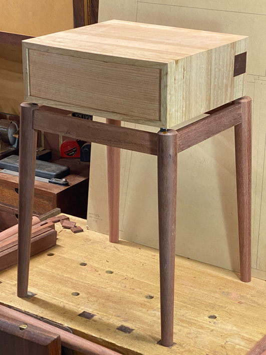
Here is the latest chapter: It's beginning to look like a nightstand!

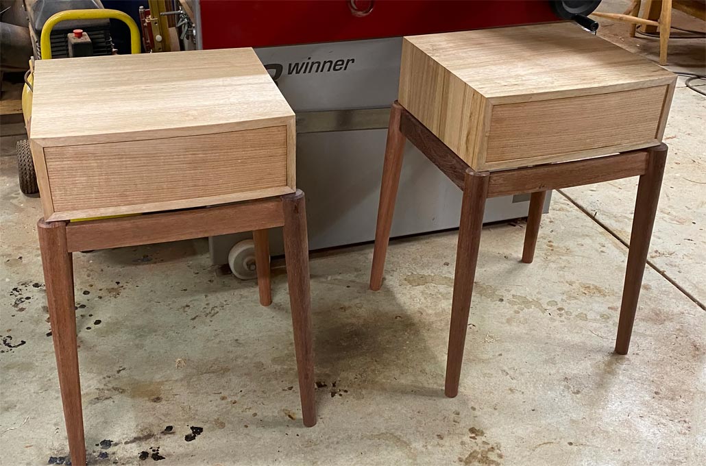
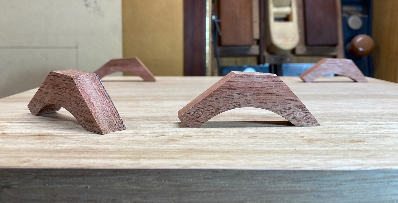
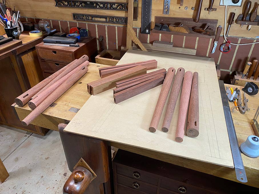
The project ended last time with all the parts cut and shaped for the two bases ..

1fa6d4f6e7c969c90af22d65b2909058.jpg


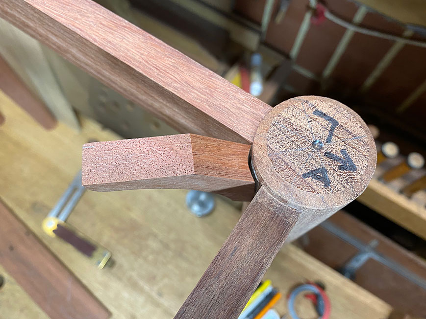
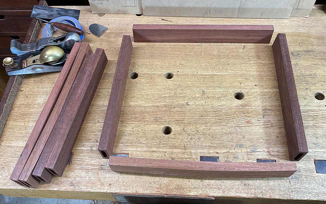
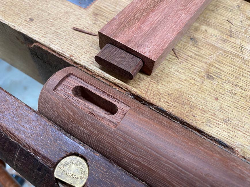
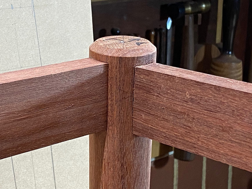
Square peg into a round hole? Not quite, but the square ends of the aprons must join flush with the round legs ...

880313d07455e0ed5bee297925c64cab.jpg


21ef22f0e060f1f501163dcc02e07b95.jpg


The choice was either to cope the end face of the apron to match each leg, or to shape the leg to match the end of the apron. I decided on the latter as each leg had a taper and the ends of the aprons were angled at 3 degrees. Matching the legs seemed much simpler. Still, it would prove to be a fair amount of work.

Step 1 - mark out the recess:

effd3e736674a1a66c11f1be1e8ccf0d.jpg


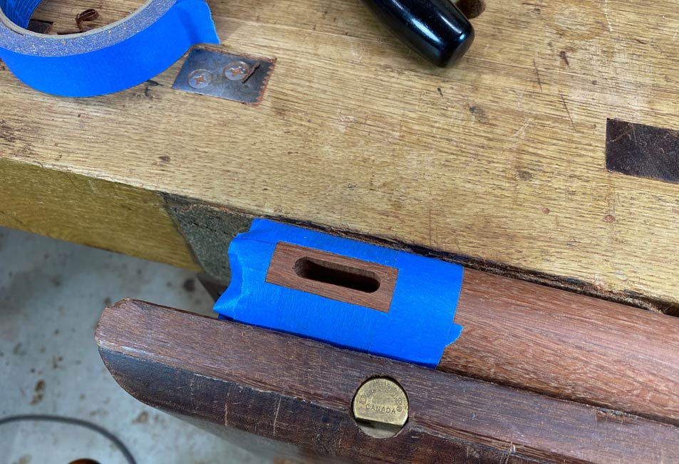
Step 2 - chop out the waste with a chisel:

c5339e46786a508343b7848c2bfda863.jpg


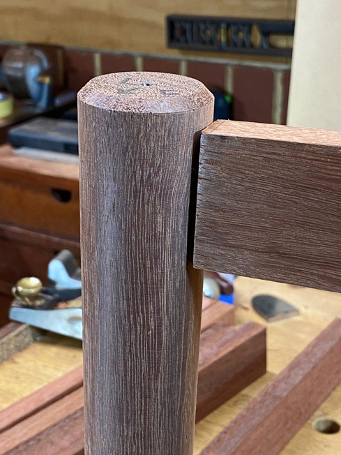
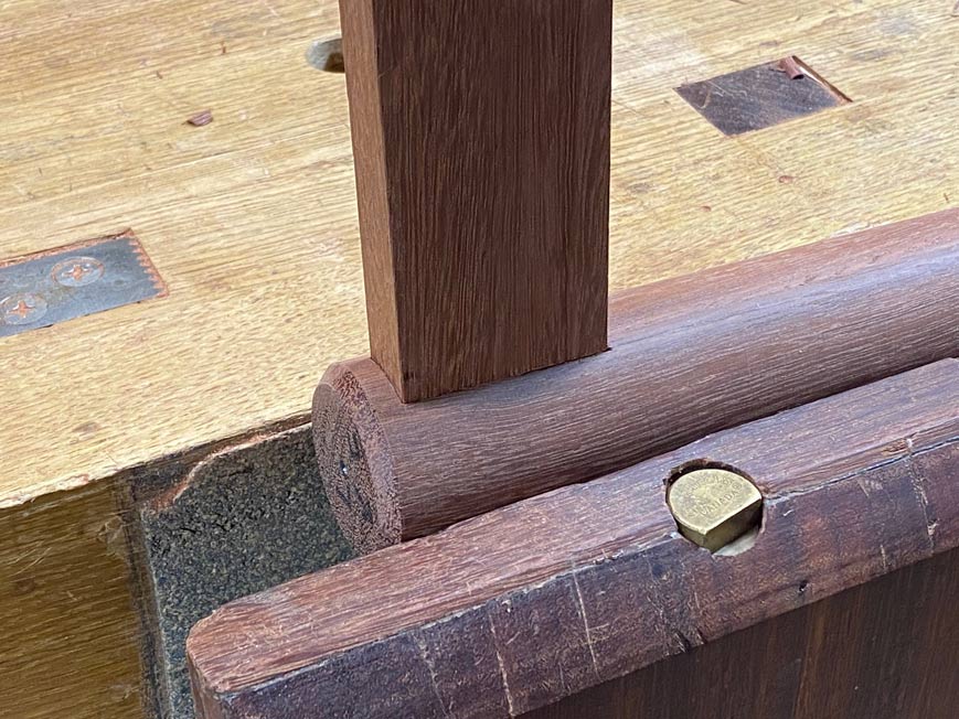
The fit is decent ...

74cc7370b165e31bb45282bafa54ddc6.jpg


81b102d156b6cabe4f7a651537278ab4.jpg


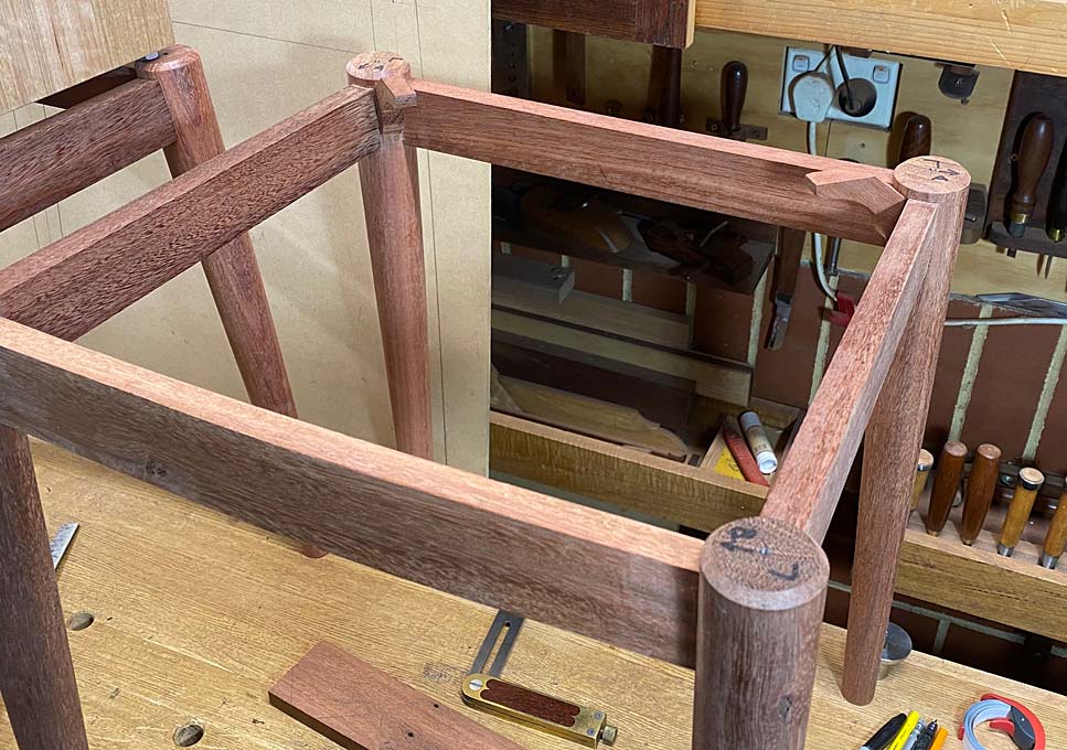
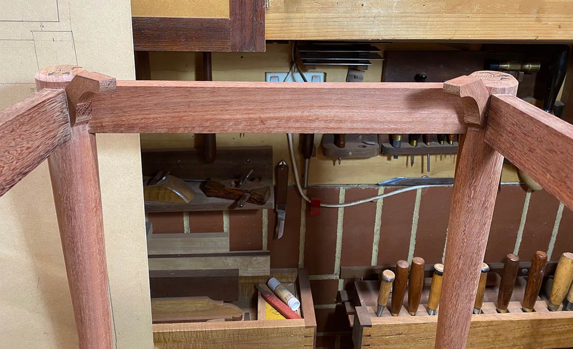
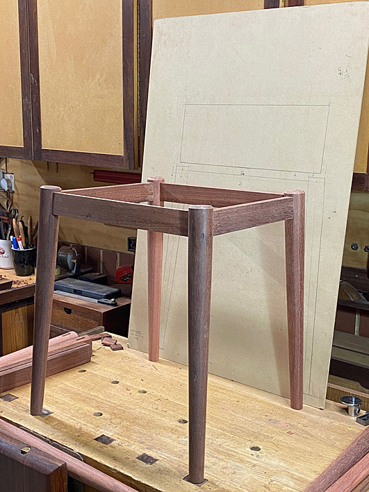
Eight joints later, and the first stage of the first base is at glue-up stage ...

15b7be182187e63f603f67abb5bc7507.jpg


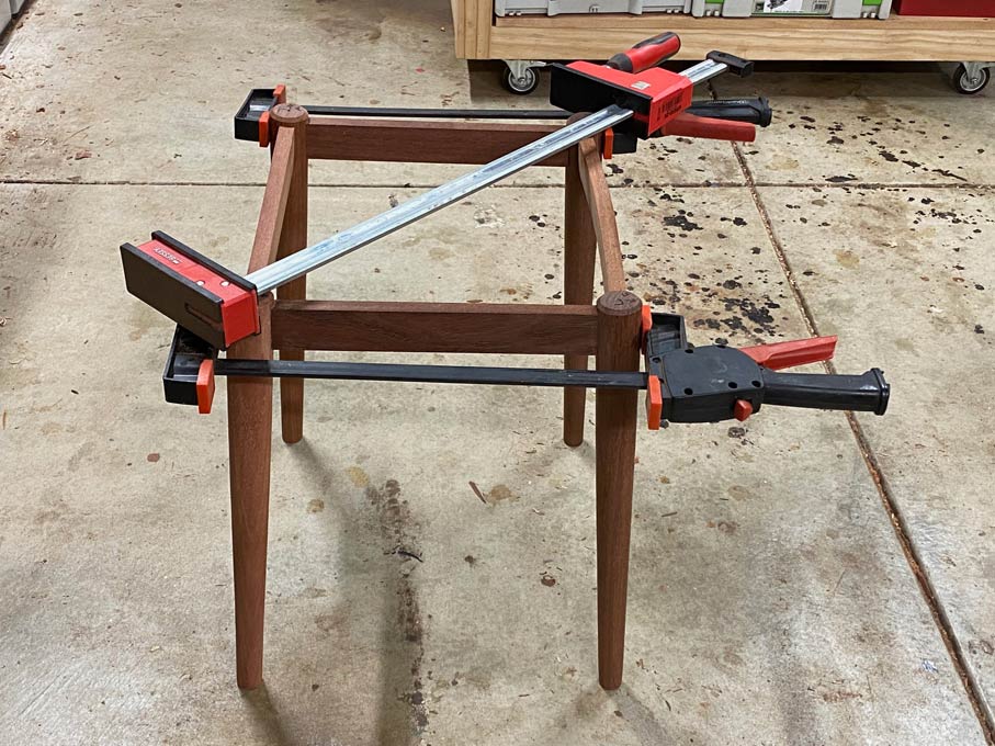
Tapers round legs splayed at 3 degrees ...

f410b53f5d67003b4d9e73724c1b9f8b.jpg


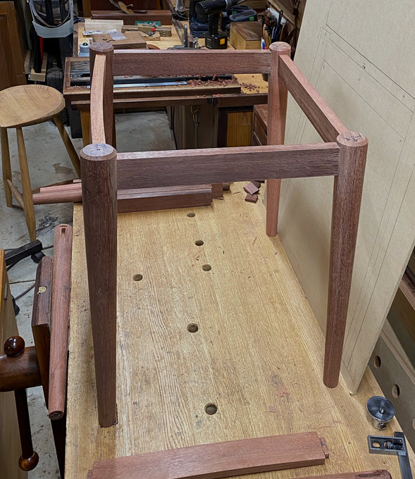
The matching rounded front can be seen here ...

35e0e819a24f47e80d0b0e2cb86c7450.jpg


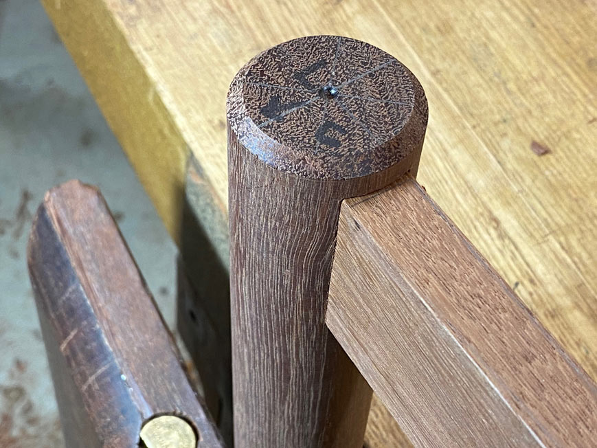
Close up of joints ...

fbc3ee572c02fb8bee63aad2aaa6957d.jpg


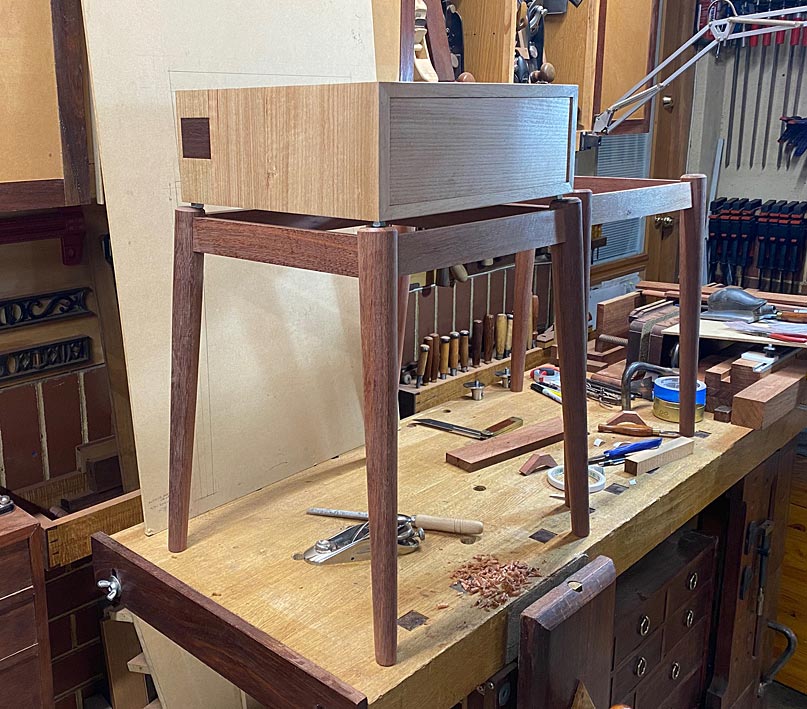
I couldn't resist a little mock-up (but lots still to do - not only that this is one of two) ...

f2774e8955306be3ce0fb654052ba1a2.jpg


Regards from Perth

Derek
 
That's really cool. I especially like the splay of the legs and the curve on the front apron.
I like the hybrid approach too. Shooting the miters to perfect them is great, but I would never consider sawing them by hand. Sawing seems to be the point where I draw the line.
I have a small pull-saw for dowels and such, and a coping saw for the obvious, but those are it.
Power sawing is so much more efficient in terms of time and effort.
It will be great to see those finnished.
 
Crazyraceguy said:
That's really cool. I especially like the splay of the legs and the curve on the front apron.
I like the hybrid approach too. Shooting the miters to perfect them is great, but I would never consider sawing them by hand. Sawing seems to be the point where I draw the line.
I have a small pull-saw for dowels and such, and a coping saw for the obvious, but those are it.
Power sawing is so much more efficient in terms of time and effort.
It will be great to see those finnished.

Have no fear, while I use handsaws all the time, these mitres were sawn on my Hammer K3 Slider, seen here using a parallel gauge ...

PowerHandTogether1_html_m46184fc4.jpg


They were then cleaned up on the shooting board.

PowerHandTogether1_html_106ba845.jpg


Regards from Perth

Derek
 
Did you have trouble keeping the ends flat? Seems like pieces with the grain going the short direction and that much width (Proportions) are usually not so stable, until the are glued together.
 
Amazing work. Do you find yourself using the #51 over the LV Shooting plane more often, or are they set up for different tasks?
 
Hi Grits

Since I have both, they may as well get used. The bevel up Veritas Shooting Plane is set up for end grain with a low cutting angle ...

AnotherCoffeeTable8_html_5ed2d8ce.jpg


The edge grain is more susceptible to tear out, and the higher cutting angle or closed up chipbreaker of the bevel down Lie Nielsen #51 controls this better.

PowerHandTogether4_html_300a1542.jpg


Regards from Perth

Spoilt Derek
 
Thanks for the reply [member=4358]derekcohen[/member] I especially like your signature there [laughing]. I enjoy reading your blog and I read up on the shooting planes quite a bit before I bit the bullet and ordered the LV. I do love the plane but I can't help looking at the #51 on LN's webpage from time to time.
 
Grits said:
Thanks for the reply [member=4358]derekcohen[/member] I especially like your signature there [laughing]. I enjoy reading your blog and I read up on the shooting planes quite a bit before I bit the bullet and ordered the LV. I do love the plane but I can't help looking at the #51 on LN's webpage from time to time.

I prefer the look of the LN, but the Veritas is the better shooting plane for end grain and edge longevity.

I started out with a Stanley #51/52, which I restored. The Stanley #51 has a poorly designed frog which is apt to break, and mine was brazed together (a reason I picked up this combination so cheaply all those years ago). When Tom Lie Nielsen mentioned that he was making an improved #51, based on the Stanley, I said I would purchase one when they were released. And that is what happened. Great birthday present, and the plane came signed by Tom. One of a kind, and it really is excellent as a shooter.

A few years down the track, Lee Valley/Veritas began designing their version. I have been road testing tools for them for many years, and received a pre-production version to this end. And that is why I have two shooting planes. The Veritas is special for its performance, and features but its modern looks may divide the audience. The traditional LN is familiar and more will be drawn to it for this reason.

Regards from Perth

Derek
 
Crazyraceguy said:
Did you have trouble keeping the ends flat? Seems like pieces with the grain going the short direction and that much width (Proportions) are usually not so stable, until the are glued together.

CRG, my apology for not responding earlier. I guess I was, and remain, unsure what you are referring to ... which "ends" are you referring to?

Regards from Perth

Derek
 
That's a lovely job, Derek. So good to see something built with care using traditional hand tools as well as this new-fangled electric stuff. Congrats.
 
derekcohen said:
Crazyraceguy said:
Did you have trouble keeping the ends flat? Seems like pieces with the grain going the short direction and that much width (Proportions) are usually not so stable, until the are glued together.

CRG, my apology for not responding earlier. I guess I was, and remain, unsure what you are referring to ... which "ends" are you referring to?

Regards from Perth

Derek

Sorry, I should have been more clear. The sides of the main case. They are considerably wider than they are long. Maybe 3 to 1? Boards like that have a tendency to be somewhat soft. The want to bow, so it's hard to get the miters straight.
 
CRG, that is an relevant consideration. I have not noticed this here. And this is an important issue for me as my drawers are always a piston fit. Perhaps as I choose and prepare the boards carefully. In this build, every board used in the case is quarter sawn. That limits the movement. I also ensure that the case is perfectly square. That limits uneven pressure or tension. Lastly, with a few exceptions (this build being one), I generally dovetail all case joinery. That locks the edges.

Can you think of other ways to guard against unwanted movement?

Regards from Perth

Derek
 
Skyhooks

Last time the nightstand build ended with a mock up of one nightstand ..

G19.jpg


Here steel nuts were used to lift the cabinet off the base. This weekend I completed the second base. Here are the two with the cabinets resting on the bases ...

I1.jpg


I had been planning to construct the floating appearance by using a slight variation of this construction ...

I8.jpg


... but the example with the nuts had me thinking if there was another way, one less observable from the side.

Here is a mock up again, taken today ...

I2.jpg


I came up with this linkage, and what I am after is some opinion as to how secure you imagine it will be.

These simply began as Jarrah triangles, and were shaped to reduce unnecessary bulk (which might be visible). All legs are 10mm thick x 18mm wide ...

I4.jpg


For greatest strength, the grain runs across the bracket.

The one side was coped to fit flush with the round leg ...

I3.jpg


This is how it is intended to be fitted ...

I6.jpg


I5.jpg


Here is the mating of the coped inside with the outside of the round leg ...

I7.jpg


The plan is to glue and screw the coped side. The glue joint should create a strong connection, and a screw will just provide extra support. The cabinets will be screwed to the top of the bracket.

Opinions and ideas?

Regards from Perth

Derek
 
Love all the details on these, from the subtle curves, to the splayed legs, and the beautiful dovetails. This is truly fine woodworking and craftsmanship to aspire to.
 
If you want more visual separation between the corner of the box and the top of the legs consider rotating the brackets 180 degrees in the Z axis, then 90* in the Y or X.

In your last pics the bracket goes up, then in at 45*, then over to get deeper under the box.

Instead, let the bracket go in, then up to get under the box. The simplest shape of this bracket is 1/4 of a ring but you’ll probably want to customize it.

It might look less strong but it really isn’t, especially after all the screws are secured. The box still rests on four screws in sheer at/in the legs.
 
[member=4358]derekcohen[/member] That looks really good. I like the design overall and this new modification too.
Though I probably would have gone the lazy route and routed the inside of the legs flat, rather than rounding the inside edge of the brackets.
 
CRG, it is actually easier to cope the ends - just use a rasp to do this.

Regards from Perth

Derek
 
Back
Top