Richard/RMW
Member
- Joined
- Jul 11, 2010
- Messages
- 2,947
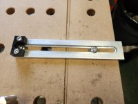
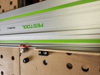
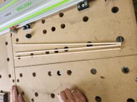
This is v3.0 and finally they are keepers, so it was worth the time to cobble together a quick video. The basic idea is to have guides that can be set anywhere on the MFT and calibrated using a story stick or gage blocks rather than measuring or using a built-in scale.
Since they are calibrated to the saw/blade/guide rail (shown at the very end of the video) then adjusted by offsetting from the edge of the rail to the black stop block they should be goof proof. It's mind boggling how often I can screw up something simple just by doing dumb stuff.
[attachimg=1]
[attachimg=2]
[attachimg=3]
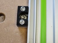
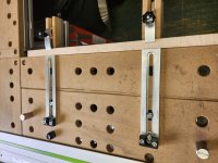
Shaper Origin & 3D printed, as usual. Secured from below with a knob, then above with a hex driver.
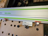
The guides can be moved to any set of holes on the MFT, so they effectively work for any measurement from zero to just under the total width of the MFT surface. I cut a lot of small parts & 90% of the time I will set them up with gage blocks.
RMW
Since they are calibrated to the saw/blade/guide rail (shown at the very end of the video) then adjusted by offsetting from the edge of the rail to the black stop block they should be goof proof. It's mind boggling how often I can screw up something simple just by doing dumb stuff.
[attachimg=1]
[attachimg=2]
[attachimg=3]
Shaper Origin & 3D printed, as usual. Secured from below with a knob, then above with a hex driver.
The guides can be moved to any set of holes on the MFT, so they effectively work for any measurement from zero to just under the total width of the MFT surface. I cut a lot of small parts & 90% of the time I will set them up with gage blocks.
RMW