TSO_Products said:
neilc said:
Nice work, Richard! I’d definitely like to see you put together a summary thread. I’ve used a lot of your techniques with 80/20 in the past and the flexibility you’ve designed is really great for a small shop or large too!
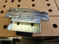
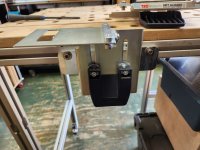
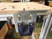
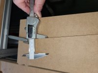
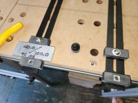
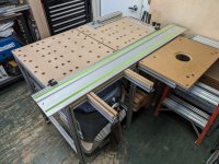
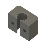
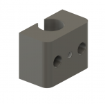
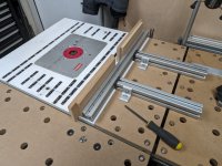
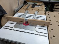
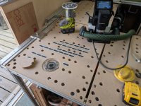
[member=59331]TSO Products[/member] Hans, I'm considering adding a guide rail hinged setup, was looking at your MFT Aligned product. Only problem is, based on photos, it looks like the bracket would stick up above the MFT top. The 80/20 slot centerline is only 1-1/2" below the surface.
Is there any reason I couldn't install the brackets upside down? It looks like all the features are centered and flipping the brackets the holes would still line up with the stock MFT hardware.
RMW
Richard,
To clarify: TSO’s
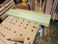
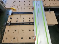
MFT Aligned is specifically designed to bring FESTOOL’s MFT/3 guide rail alignment up to our customers’ higher expectations by addressing the limitations in the design of the OEM hinge bracket assembly and guide rail support.
We kept all the OEM components which are up to the task and replaced and added additional components allowing the user to achieve the highest possible rigidity while maintaining height adjustability.
Our MFT Aligned set (front and back) does not contain complete hinge assemblies. In other words, you would have to obtain a set of MFT rail hinge assemblies and rail support.
We are working on a completely self-contained hinged support system for 20mm hole top surfaces but that is still over the horizon.
Keep up your inspiring work and posting on the FOG!
Hans