Split Top Roubo MFT with Benchcrafted, Incra and 80/20

Sean KS

Member
Joined
Dec 14, 2012
Messages
110
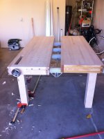
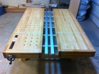
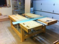
I am building a split top roubo that integrates a festool guide rail. The top slabs are 26"76"3" with a 8" split and build from mostly hard maple. The center support beam (underneath the split) has t-tracks with t-track locks to accept an Incra TS positioner and keep it parallel to the track. The aprons have two sets of parallel t-tracks to support a festool style bracket for the guide rail. I am not using the original fence on the Incra positioner, I opted for a 80/20inc extrusion that is .5" thick so that the fence can slide under the festool guide rail and cut stock as thin as the fence dimension. Placing the "rip" fence below table surface provides the capability of ripping thin stock, but more importantly, allows you to use the Incra-Festool system for narrow rips. For safety I position the fence to the right side of the track to eliminate the risk of kick back from pinning both sides of the cut. The system will also utilize an Incra miter gauge with a custom bracket that attaches in similar fashion as the Festool MFT systems.
I'm having the top slabs CNC bored with 3/4" holes so I can use qwas style dogs for all alignment, and veritas bench accessories. The thickness of the slabs will make this bench useful for hand-tooling work and also allows for the installation of the Benchcrafted Tail Vise.
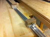
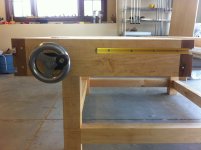
The bench will be used for routing as well. For example end grain slot mortises using the apron t-tracks to position the work piece. I used a partially built apron, the Festool guide rail and stops, and a microfence interface to cut the slot mortises in the apron joint mockup. The dual t-tracks worked well for orienting the piece for the cut. The joint is drawbored with brass dowel. I have a couple of rough sketchup screen shots and one of the apron joint mockup. I have more pictures of the build process if anyone is interested.
 

Attachments

  • image.jpg
    image.jpg
    1.9 MB · Views: 6,257
  • image.jpg
    image.jpg
    884.8 KB · Views: 7,826
  • image.jpg
    image.jpg
    1.5 MB · Views: 4,669
  • image.jpg
    image.jpg
    1.5 MB · Views: 6,769
  • image.jpg
    image.jpg
    1.6 MB · Views: 3,208
  • image.jpg
    image.jpg
    539.7 KB · Views: 5,154
I'm very interested in seeing more photos and build progress. Brilliant use of the Incra positioner recessed into the trough!

From what I can understand you will be using the Incra jig to secure a guide rail and move it into position to make your cuts. If this is correct then you will probably end up with a lot of cut lines in your top over time. Is the top maple or did you devise a way to secure replaceable MDF sections?

Thanks for sharing.

RMW
 
Neat idea, but I have the same comment as RMW.  It would be a shame to make cuts into the top if you're using a TS 55 and guide rail for cross cutting. Can you show us some examples of how to you're going to use the fence system?
 
I just looked at your plan again and had an idea. What about adding a sacrificial, replaceable strip routed across the two slabs where you would place the TS guide and make the cross cuts. You could route a groove and place 3/8 hardboard or wood strips. It would be placed at the far right of the bench and you could add a flip up extension table to hold long pieces.
 
Whoa,
That's a badass idea. Please show us more. Also. I'd love to have that sketchup file if you are willing to share.
 
Great idea and sketchup drawings!  I'll be watching this thread for followup pictures as it progresses.  I'll add some advice: if you are planning on using the tail vise for hand planing,  be sure to fabricate some stout legs.  The MFT as it stands is just too flimsy for hand planing.  If you are using it just for clamping pieces for sanding or routing, MFT legs are adequate.  
 
Well, that's a piece of a workbench (third image :)

Seems to be a great bench. And it's going to be beautiful as well. I'll be really interested in your build pics. Please post them. Could you elaborate some about how you will use the Incra positioner. Will it position your guide rail or your wood? I suppose it's the wood.. And I suppose that you intend to use dogs for lining up the wood? How do you attach the fence to the Positioner when it's in this low position relative to the bench surface?

//Michael
 
Michael,
Thanks for the complements, lets hope the finished bench looks as nice as the mock up joint.
I drew up a quick model of the bracket that attaches the guide rail to the t-tracks in the bench apron. The bracket is able to adjust with screws to make 90 degree cuts. The top is CNC bored so I will be using the dog holes for referencing the guide rail bracket to 90 degrees. The screws set the bracket to that angle even if I removed it and placed somewhere else along the apron t-tracks. The wood will reference off of an Incra miter gauge that will attach to the aprons with a similar custom bracket. The end result of the miter gauge and the guide rail bracket will effectively make the bench operate like a Festool MFT. The Incra positioner just allows me to make repeatable cuts, or adjust the work piece for lets say a fluting application. Hopefully it explains how the bench is used.
The Incra positioner will have a 80/20 extrusion that is 1/2", 2", 48". It attaches to the Incra postioner in place of the table saw fence it comes with. The thin dimension will be able to slide under the Festool guide rail when I am working with thin stock that I want ripped to dimensions less than the guide rail itself.
 
Really great idea. But I'm not entirely sold on the guide rail bracket idea. It seems to be a little slow to work with in regards of adjusting height and changing wood for the next cut. But I might have misunderstood.

You could also offset the 80/20 fence to gain some cutting width. I.e. the workpiece would lie over the positioner instead of at the end of the positioner. You could have two interchangeable brackets for this. One that puts the fence at the end for small cuts. And one for offsetting the fence towards the lock handle of the positioner.

If the trench for the positioner is deep enough you might want to think about putting a lid on the trench. I can imagine that the trench will be annoying if you use the table as a mounting table. And also, you'd not want to have glue dripping on your positioner.

//Michael
 
I will see how the bracket works in terms of speed. If it takes too much time to get the next work piece into position  I will hinge it.
The Incra positioner is intalled via t tracks. So I can move it anywhere along the length of the bench. If I need 2 more inches of cutting capacity I can move it down the t tracks to accommodate the cut. This also means I can remove it durning glue-ups. Roubo troughs are generally not this wide I admit, I'll see if a lid would come in handy when I start using the bench in practice.
 
In the third image I originally posted you see that the dado for the t track turns onto the end grain. For the mock up joint I turned the piece vertically on the router table to make this cut. For the actual project this dado is on the end of a 7' work piece, so I cannot turn in upright on the router. I tried on a practice piece to make the cut with a hollow chisel mortiser, but even though it was well backed it blew out in fantastic fashion. My second attempt was making the cut with a razor saw and chisels. I got the dado I was looking for and proved that the method works.
 
Perfect, just remove the positioner if you need room for the lid ;)

About the offsetting of the fence. I didn't mean to gain two inches. I meant a bracket that offsets the fence furhter back. All the way to the locking unit. This gains cutting width without having the positioner protrude outside of the table. But I'm probably biased in the hunt for inches since I'm in a really small shop myself.

I'm looking forward to seeing more of your images.
 
I LOVE the idea of the positioner with the 1/2" 80/20! Simple to zero out to the guide rails and infinitely adjustable.

A suggestion perhaps in lieu of the guide rail bracket: add a retractable pin on each side of the bench, slide them up and just hold the guide rails against them align it. I was playing with a similar idea a while back and did a (very bad...) video illustrating the idea:


In my example I use the rail clips from my Rip Dogs to align the guide rail to the pin but you don't need them, just press the edge of the rail to the pins like Peter Parfitt's Parf Dogs.

Thanks for sharing your ideas.

RMW
 
i like that rmw.
really glad to see this coming along

this sytem would allow for angled cuts as well. just move the block along the rail  to adjust it.
or even put one on the short extrusion and the other on the long.
 
RMW, Your rip guides are awesome. Much sleeker and more user friendly than a huge bracket. I'd be hard pressed to get the smooth friction fit you've worked out, do you see any issue with using a handwheel with a screw mechanism to adjust the height?
 
RMW, Here's what I mean, it just took a minute to draw it up. It's the same basic idea, I've put in a height locking screw. And it attaches to the T track underneath the Festool Guide rail. The Height Adjustment Rod (HAR) has a threaded rod at the top so that the HAR can be rotated by hand to lock the t track nut to the Festool Guide Rail. I like this design much more than the big bracket idea, do you see any issues off the bat? Michael what's your thoughts?
 
I think you over complicate it a bit. You don't need precision in the vertical movement (as with your HAR). The vertical position is automatically calibrated by the surface of your work piece. What matters is the alignment to the MTF holes, and in your case even to the LS Positioner fence.

Parf dogs or RMWs Rip dogs will solve this. If you want something even sturdier you might want to go with angle brackets as I use in my build. You can se the brackets in this image:
[attachimg=#]
 
Sean,

You idea is right on the money, except as Michael states it does not need to be as complicated as having it attached to the t-slot underneath. Just extend the pin a couple inches over the MFT top and let the guide rail press against it the same way it does with Michael's brackets.

Here are some old photos from my first attempt:

[attachthumb=#]

[attachthumb=#]

[attachthumb=#]

[attachthumb=#]

[attachthumb=#]

I used the clips on the guide rails because I was working on a similar idea at the same time and I had them lying around but they are not necessary with the pins mounted this way.

Otherwise I think your design will work perfectly with the thumb screw tightening onto the pin.

RMW

 
I also believe that these height adjusters are far more complicated than need be.  But more importantly, these designs do not offer any support to keep the guide rail parallel with the surface of you bench.  Festool's guide-rail brackets support the rail for the bulk of the width of the rail -- most of the distance from the back edge of the rail to the splinter guard.  Without this support, the weight of the saw on the rail will cause the rail to tip. 
 
Rmw and Michael, the reason I like locking the guide to the braket is cause I use the guide with a Mirco Fence interface for routing operations, such as hardwood dadoing or sliding dovetails. This action puts a good amount of torque on the guide rail and I'd be afraid of slipping off the HAR and coming out of alignment during te routing operation. The TS 75 doesn't cause concerns in the same regard. You guys have used the pins in real time, do you think my concerns are grounded in terms of routing operations? Thanks for your thoughts!

Corwin, What type of operations are you concerned about tipping occurring? In rip operations the work piece supports the guide rail so tipping can't happen then. Even in narrow rips using the incra positioner the guide rail has support. I can see certain routing operations causing worry but a piece of scrap material very simply remedies that worry. I can only guess your concerns are regarding cross cuts where the workpiece does not extend under the guide. A rare cut that I would opt for using the table saw. If I needed to do this cut with the TS 75, let's say on a very long board, once again a scrap block would support the guide from tipping. I see big advantages in having a single round contact point in the guide rail braket for ease of alignment, an issue that the festool system fails to solve with much confidence. Can you please describe what procedure your tipping concerns would pertain to if I am missing something?
Thanks for your guys help it's extremely beneficial
 
Back
Top