TS55 - Guide Rails - MFT3

Charlie Hill

Member
Joined
Sep 20, 2013
Messages
41
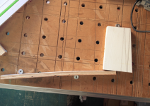
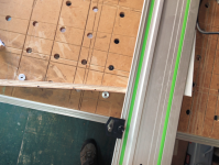
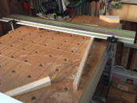
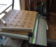
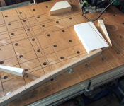
I have been trying to cut some small pieces of oak on the MFT3 with TS55 and find that the guide rail does not stop the workpiece from moving as the blade starts the cut. This results in an out of square cut [eek]

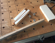
The pieces of oak are 50 mm x 50 mm and 40 mm thick.

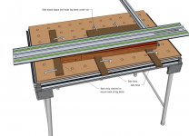
The problem may be caused by the grip strips on the underside of the guide rail not being in contact with the oak. Can more grip strips be attached to the guide rail closer to the splinter guard side of the rail and would this eliminate the problem?

Or is there a better solution?
 
a common method here is to set up cuts so that the larger part of the board is under the rail, in contact with the rubber strips, and to take the offcut as the final measured piece.
basically cutting small strips from a larger board, measuring your cut on the right side of the blade.
then cross cut your strip to final widths.
 
Charlie,

I needed to rip some wedges last week and had a similar issue, compounded by needing to adjust the wood at different angles. The solution was to use 3 dogs plus a scrap of plywood to spring-clamp the stock under the rail. One dog is a stop for the material, the second is the pivot point for the spring lever and the third holds the lever once tension is applied.

[attachthumb=#] 

[attachthumb=#] 

[attachthumb=#] 

[attachthumb=#] 

[attachthumb=#] 

[attachthumb=#] 

An alternative would be to use the Festool clamping elements to hold the stock. In this case that would not work, as I also needed to adjust the material while the rail was in place to line up the cuts to my marks. It worked really well, as I could just slide the material around and the spring tension held it in place.

RMW
 

Attachments

  • Wedge1.png
    Wedge1.png
    994.9 KB · Views: 458
  • Wedge2.png
    Wedge2.png
    1.1 MB · Views: 378
  • Wedge3.png
    Wedge3.png
    965.4 KB · Views: 424
  • Wedge4.png
    Wedge4.png
    1.1 MB · Views: 2,792
  • Wedge5.png
    Wedge5.png
    938.9 KB · Views: 378
  • Wedge6.png
    Wedge6.png
    1.1 MB · Views: 644
Richard/RMW said:
I needed to rip some wedges last week and had a similar issue, compounded by needing to adjust the wood at different angles. The solution was to use 3 dogs plus a scrap of plywood to spring-clamp the stock under the rail. One dog is a stop for the material, the second is the pivot point for the spring lever and the third holds the lever once tension is applied.
OK this a Great Idea !
this 1st pix & description goes into my  " MFT set-up saved Idea "  folder  [tongue]
 
Hey,Richard, very nice idea.  That looks to be about a 7 degree angle...do you have the actual angle measurement?  Thanks. 

PS...possibly a slick way to taper legs?
 
NYC Tiny Shop said:
Hey,Richard, very nice idea.  That looks to be about a 7 degree angle...do you have the actual angle measurement?  Thanks. 

PS...possibly a slick way to taper legs?

The angle on the wedges? No, I just used some random angle.

RMW
 
Great idea.

I just cut tapers on table legs using the MFT/3 and TS saw. 

I used two indexing sticks under the rail secured with screw clamps to the table to set the angle which I had marked on the leg face and aligned to the rail guide strip.  Used one clamping element to pinch the leg between the fence and the clamping element under the rail.

I did have to use two sacrificial pieces clamped outside the leg to the right of the fence to hold the legs in place before cutting.  But all four legs were cut with two tapers with complete accuracy.  So much safer and more accurate than a table saw with taper jig.

Two strokes to clean up with a hand plane and I was done on each side!

neil
 
Neil, sounds brilliant! But, after a bottle of wine, there's no way I can follow all that.  Could you possibly post a few pics of what the heck you are talking about? Thanks, much!
 
OK -

Here's a drawing of the layout I used to cut the tapered legs...   Fortunately, Festool components are in the Sketchup 3D warehouse to make this easy!

[attachimg=#]

The red area represents the taper that is removed and then the leg is rotated 90 degrees and a second cut is made while still referencing off the positioning pieces to hold it tightly in place.

A positioning side reference board under the rail aligns the leg for repeatability of cuts.  The leg is against the fence at the front and held in place by a strip at the back that has a notch the width of the leg (2" in this example" that holds the back of the leg in place.  The right side of the leg is held against the positioning reference board by two small pieces of wood to keep the leg tight in reference.

Not shown are blocks under the rail to keep it a consistent 2" thickness to match the leg blank.

When I cut this, I used the MFT rail guides, though they are not shown in this drawing.

By comparison, in the past I've used a table saw to taper legs, or a joiner to do so, but this really worked accurately and quickly.  And it's also a lot safer and cleaner!

neil
 

Attachments

  • table with leg jig.jpg
    table with leg jig.jpg
    368.4 KB · Views: 1,275
Thank you, Neil! This is great! Yes, I can imagine this being safer than other methods.  Wonderful! Also, nice sketch-up skills, Bravo!
 
Back
Top