George,
Welcome to the FOG! Great news for 1080 owners! Thanks for sharing.
Peter
Welcome to the FOG! Great news for 1080 owners! Thanks for sharing.
Peter
Just_George said:First of all, thanks Paul for yet another great review!
Next, just as an FYI: To those who own the older MFT 1080 or 800, the clamps used by Paul to secure the fence to the rear rail (originally used on the end of the fence...) are not in the Festool catalogue, nor are they shown as an assembly on Ekat. The individual components are shown, but not the assembly. :-\ A quick call to Chris at Festool Service reveals that there IS indeed a part number for the assembly. Order part #120 (yep, that's all) and the service dept. will assemble the components and send it out, all for a grand total of $6.00
Hope that helps somebody...
PaulMarcel said:Maybe give Festool USA a call to order the part. Maybe the listing you are seeing at $58 is for a larger assembly including a fence unit and something else. Dunno. That seems more like the price of the whole thing (clamps, fence, flag stop, etc) back on the 1080.
Sparktrician said:Following up on Paul-Marcel's review of the MFT system, I took it upon myself to create a calibration method similar to the one that Paul-Marcel did for the MFT 1080, but for the MFT/3.
Calibrating the MFT/3's fence to the Guide Rail
coezoo said:Sparktrician said:Following up on Paul-Marcel's review of the MFT system, I took it upon myself to create a calibration method similar to the one that Paul-Marcel did for the MFT 1080, but for the MFT/3.
Calibrating the MFT/3's fence to the Guide Rail
Thanks for taking the time to do this!
But, all of the links to the larger photos are dead. I'd love to be able to see the larger photos to go along with your great write up. Do they still exist somewhere else?
Thanks
Sparktrician said:Following up on Paul-Marcel's review of the MFT system, I took it upon myself to create a calibration method similar to the one that Paul-Marcel did for the MFT 1080, but for the MFT/3.
Calibrating the MFT/3's fence to the Guide Rail
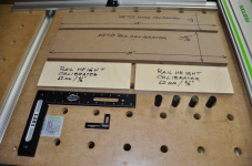
1. Initial planning. You'll need the following items (or their equivalent):
Note: width and length are rather immaterial; only thickness counts on this calibrator.
- Fence Calibrator (24” x 3 7/8” x 3/4”)
- Guide Rail Calibrator (24” x 5 23/32” x 3/4”)
- Rail Height Calibrator (4” x 12” x 1/2” [or 12 mm])
- Qwas Dogs (set of four)
- 12” x 8” reference square
- Mini-square
- MFT/3 equipped with:
- FS1080 guide rail and mounting hardware
- Fence and miter scale
[attachthumb=#1]
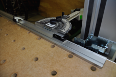
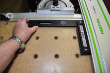
2. Using the Mini-square, verify that the cut-away end of the fence lines up with the right side of the miter gauge.
[attachthumb=#2]
This will provide 1 1/8” clear space between the end of the fence and the cut line in the MFT.
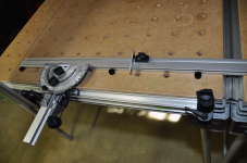
[attachthumb=#3]
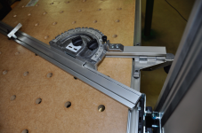
3. Loosen the fence clamp top knob releasing the fence.
[attachthumb=#5]
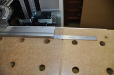
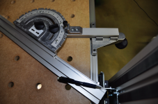
Loosen the miter gauge in/out motion adjustment knob.
[attachthumb=#4]
4. Insert three Qwas Dogs in the second row of holes from the back of the MFT top. Lay in the MFT/3 Fence Calibrator between the fence and the Qwas Dogs. Hold the fence tightly against the Calibrator and the Qwas Dogs. Tighten the miter gauge in/out motion adjustment knob to lock it in place. While still holding the fence against the Calibrator, tighten the top knob of the fence clamp to ensure that there can be no movement of the fence.
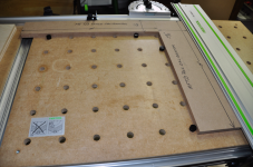
5. Lay the two 1/2” (12 mm) Guide Rail Height Calibrators in place under the guide rail, then drop the guide rail into place and adjust the height of the guide rail down to meet the Height Calibrators. Now remove the Height Calibrators.
6. Once the guide rail height has been adjusted, place two Qwas Dogs in the 6th hole column (from the left) and in the 3rd and 7th holes from the back of the MFT/3. Insert the Guide Rail Calibrator between the Qwas Dogs and the side of the guide rail. The rail should be snug against the Guide Rail Calibrator.
[attachthumb=#6]
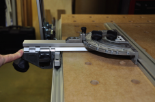
7. Use the 12” x 8” reference square to validate that the guide rail is perpendicular to the fence.
[attachthumb=#7]
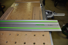
8. With the fence now adjusted fully to the rear, the MFT/3 will accommodate material at a maximum width of 27 1/4”, more than the piece of ornately-figured and rare Georgian MDF shown in the photo.
[attachthumb=#8]
9. The fence can be moved out to the third row of holes from the rear of the MFT/3 by using Qwas dogs to ensure proper alignment. As before, use the 12” x 8” reference square to validate the intersecting angle of the fence and guide rail. Note that there will be some play in the fence unless the fence clamp is moved to the left side of the MFT/3 and engaged to lock the fence into register. This setup will accommodate stock widths of up to 19 5/8” and brings the stock closer to the saw operator to reduce reaching. Note that the in/out adjustment of the miter gauge is almost at its maximum point.
[attachthumb=#9]
10. If one is using conjoined MFT/3s, the placement of the fence clamp between the MFT/3s is not possible. If absolute squareness is required, place three Qwas Dogs behind the fence, loosen the miter gauge in/out adjustment knob, the slide the miter gauge back tightly against the Qwas Dogs and tighten the in/out adjustment knob. Leave the Qwas Dogs in place to ensure squareness. This position will allow a maximum material width of 20 1/2”. Moving the Qwas Dogs to the rearmost row of holes will allow a maximum material width of 24 5/16”. Note that to retain absolute squareness, one should leave the Qwas Dogs in place behind the fence, since the fence clamp can't be used in this position.
[attachthumb=#10]
[attachthumb=#11]
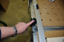
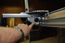
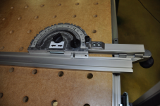
11. Moving the fence to the maximum extreme of the in/out adjustment will allow the fence to rotate up to 90 degrees clockwise, and up to 55 degrees counter-clockwise before the fence hits the rear guide rail pivot mount shown at the end of the pencil.
[attachthumb=#12]
This angle can be increased to 63 degrees by moving the fence to the left so that the fence guide pin is just inside the fence extrusion.
[attachthumb=#13]
Moving the fence 1/2” further to the left past the alignment pin will allow full 90 degrees of counter-clockwise rotation, and will give the fence a full 180 degrees of rotation.
[attachthumb=#14]
Note that when the fence is rotated, use of the fence clamp is advisable to retain best accuracy of cuts, but will necessitate breaking apart conjoined MFT/3s to accomplish this.
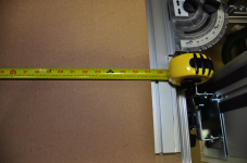
12. Note that if you cut your calibrators to a precise 24” length, and choose to apply measuring tape to the fence, you can use the 24” Calibrator length to validate that the 24” marker on the tape is at the exact point to get a good 24” cut at the guide rail. The Fence and Guide Rail Calibrators can also be used to set the height of the guide rail to 3/4” or 19 mm.
[attachthumb=#15]
[smile]
thedevme said:By any chance does anyone have the pictures explained in this comment saved or has done a similar setup - I would really like to see a few of these images up close. Thanks in advanced.