smorgasbord said:
Packard said:
A tolerance of +/- 0.010” (+/- 0.254mm) is probably all that is required for standard woodworking joints.
Even if I were to believe that, a simple 2" wide, 4-sided mitered frame where each piece was cut 0.2º off (the spec for the digital angle gauges) would result in 3 joints that fit and one joint with a gap that's 5 TIMES the tolerance you desire. Even spreading the gap evenly among the 4 joints would result in a 0.014" gap, larger than your spec.
Use wider pieces, or try making a hexagon or octagon and things deteriorate rapidly. Which is why all the YouTube videos about cutting slightly under to have the gap inside a miter, or using a screwdriver shaft to push the wood fibers into the gap.
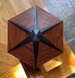
Here's a staircase newell topper I made a couple years ago. A 10" point to point hexagonal shape built from 12 pieces plus a center piece. Note how the ebony pieces taper to almost a point and that the center piece's sides matches the width of the ebony tapers. Also this is in 3D as the center is a few inches higher than sides. And above a handrail, it's about 4' high, so as you start to climb the stairs it's at eye level, and you're looking right at it as you descend. Tell me what kind of accuracy you'd tolerate for this.
[attachimg=1]
I will give a comparison.
Colt Firearms factory is by almost anyone’s definition, a huge machine shop. Most of their machine shop work is to a tolerance of +/- 0.002” (two thousandths).
Their revolvers, especially their Python line is to a tighter tolerance. But since many of the parts are hand fitted using fine hand-held honing stones, it is impossible to exactly quantify the tolerances.
The tightest tolerance in the revolver line involves the fit of the side place to the frame. It is estimated that the tolerances are +/- 0.0001” to 0.0002”. (One tenth of a thousandth to two tenths of a thousandth.
Here is a hand fitted side plate. You can see where the place meets the frame where it bisects the small screw, just behind the trigger under the grip and near the hammer near the cylinder release.
My old Colt revolver (not a premium Python) had a side plate so carefully fitted that you had to hold the gun at a certain angle to the light to see the seam. That weapon was made in blued steel. The stainless steel versions have seams that are easier to see.
But those extremely tight tolerances do not define the overall production. It applies to a few finely hand fitted pieces.
The same applies to woodworking. If you are making a nice jewelry box you are working to one set of tolerance. If you are adding marquetry, another set of tolerances, and the shelf to display it, another set of tolerances.
But for 90% or more of woodworking, tighter than 1/32” is not required. While hand fitted pieces could be made to much tighter tolerances.
If you are using a ruler or the markings on a fence to make your cuts, then I think 1/32” is about right.
My chop saw is calibrated in full degrees. So to is my miter gage on my table saw.
But the 45 degree cut on my dedicated miter saw is factory set and more accurate than my measuring tools.
And my Lion Miter trimmer is calibrated (by me) to an exactness that is as perfect as I can measure for 45 and 90 degree trims.
Those two miter devices are the most accurate in my shop and were needed for picture framing. For other miter situations they are overkill.
So, unless you are taking measurements with huge vernier calipers, I doubt that much closer tolerances can be held.
Hand fit pieces may be to much tighter fit, but not usually by using measuring tools.