arso_bg said:
Maybe we could share some information to solve common problems.
Absolutely!
")
arso_bg said:
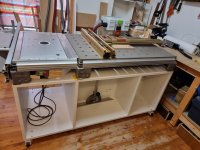
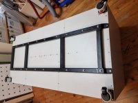
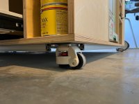
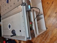
While constructing the cabinet I was thinking about how to prevent the cabinet from sagging in the middle.
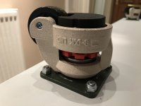
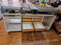
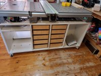
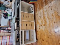
Me too. The challenge for me was maximising the usable space, so I discounted one of the options which was creating a torsion box for the base as that would have reduced storage and drawer space. I had some specific dimensions I wanted to achieve to be able to store various things. Four castors wasn't enough and the middle sagged. Then I added two more in the centre, and when they were adjusted such that the MFT and CMS top was level, the drawers bound on the bottom! So I then removed the centre two and added two more into the mix; total now eight. So with castors at each corner, and then castors under the two vertical stretchers, I have a level surface that is 900mm in height.
arso_bg said:
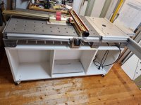
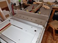
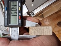
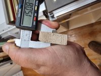
The shims that you see in the pictures under the MFT feet were necessary because the rubber feet of my MFT table are strongly deformed.
You can buy the feet as a spare part if you want to; they aren't very expensive. The part number is 492255 for a set of four. I replaced all of the ones on my old CS 50 as they had aged and weren't very rubbery any longer!
arso_bg said:
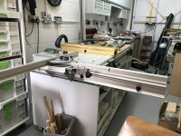
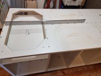
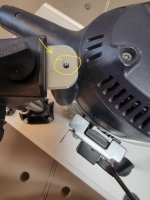
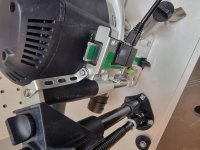
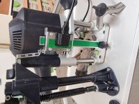
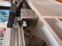
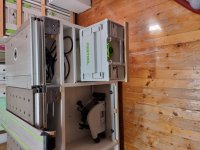
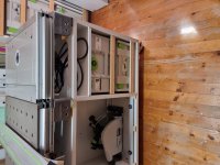
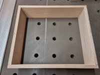
I see that you use the TS 75 module and also the router module. Do they both sit level in the VL-CMS? Because my OF 1400 module sits perfectly level in the CMS, but the TS 75 module sits a little below the stretchers mounted in the front and back part of the CMS - maybe some 0.25 mm
I don't actually use the TS 75 module in the rolling cabinet (I use it in my CMS-GE) but I wanted to make sure that the hole that I had cut in the top and the permanent shelf height would allow all of my modules to fit and work without issue if I needed them to. Indeed, I now have the parts for an INCRA Mast-R-Lift II (Metric) with AUKTools 2400W Fixed Base Router Remote Speed Control so will actually be fitting that in place of the MFT/3-VL. Next project... ;-)
With regard to the module not sitting flush, I've not had that issue. If anything, the TS 75 module sits slightly higher for me.
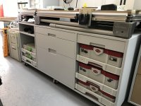
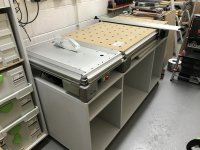
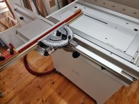
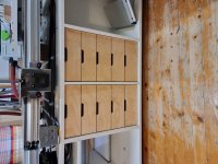
Of all the features, my favourite is the centre drawers. In the top drawer, to hand are all my marking, measuring, drawing, cutting, taping, glueing, etc. tools and various odd bits that I use frequently. I was always hunting around for them previously but now they're right at my fingertips. The second drawer then has all my clamps and dogs, and the third has various VAC SYS components and some other bits and pieces. It works so well.
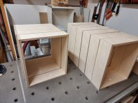
There are no photos of the back yet but the layout is almost the same. Only the section with the MFT/3-VL above is straight through. The middle and far right sections have an intermediate panel, and the plan is for the rear right section to house the VAC SYS compressor and the rear centre section to house my extractor.
Like everyone, just need to find the time to finish it!