smorgasbord
Member
- Joined
- Jan 7, 2022
- Messages
- 1,370
After fixing my router and installing a MuscleChuck (see https://festoolownersgroup.com/threads/this-morning-was-fix-my-router-day.76878/ ), I decided I really needed a better/new sub-base. With the MuscleChuck, the bottom of the collet now plunges about 15mm below the metal base, so there's no reason not to have a thick sub-base, which opened up the possibility of rigging something up to use my router with my track saw tracks.
I've been of the thought that the way Festool's router to track attachment works is kind of kludgy - the router rides on part of the track, so it's lifted off the surface, but the other side of the router's base needs to have that little support bracket installed to compensate. You can see Sedge go through that process here:
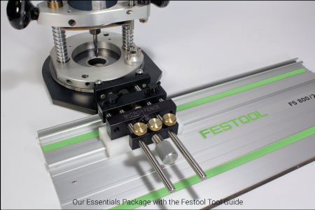
Now, I've got a Micro-Fence edge guide for my router, which is pretty darn good, and I thought about buying their adapter plate (which they call an "interface package" just to confuse us) to use it with the Festool tracks:

But, that deal requires a whole new sub-base and costs a few hundred dollars on top of what I already paid for the edge guide! Even trying to just get some of the parts and cobbling some things together with their micro-adjust that I already own would cost me $115 minimum, and no guarantee I could get it to work. I did have to invert the guide rod attachment plate to accommodate the thicker sub-base, but that actually worked out really well - but I suspect it's something particular to my 1613EVS router and the way Micro-Fence does things.
One nice thing about being able to make my main sub-base thick is that it's now thicker (12mm) than the tracks. This gave me an idea for a simple track rider attachment.
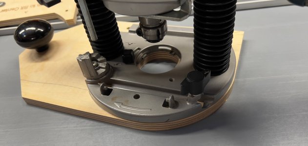
Now, the whole idea behind the Festool and Micro-Fence setups (and I'm sure there are others out there) is that you get a micro-adjuster to set the track to router bit distance. I'm usually all over any kind of micro-adjust jigging, but, for now anyway, decided to go simple. Here's my prototype base (the latest one is cut along that drawn line, btw):

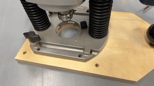
Here's a view from the other side:

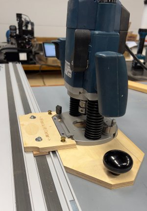
This gives me two straight edges to guide/align against, about 120º of curved base because that's usually better against a straight edge if not locked in, ability to mount my micro-fence edge guide, plus an extension with knob for edge routing stability. The sub-base mounting holes have zero slop (maybe even a slight interference fit to the bolts), so getting those dimensioned right was critical (and worked first time due to Bosch using whole number millimeters). This means the curved part of my sub-base can extend beyond the metal base just slightly and still be accurate enough relative to the bit center that where on the curve I'm at doesn't practically matter (it's 85mm). I also made the straight part of the sub-base extend beyond the metal base, also at that 85mm dimension to keep things simple as well as to provide a place to mount my track riding attachment:

These will be made of phenolic for the final version. You can't see it, but the thin piece that rides in the track has two 2mm nibs sticking out to register against the rail (you can see the gap they cause) which I think will help friction wise. The two nuts on top will be replaced by small knobs when they arrive in a day or two. And that's how the fit to the rail is adjusted - push the main sub-base against the track then then pull the knobs towards the router and screw them down. The thin piece is just thick enough to barely graze the teflon-like track runner.
And because of the way I dimensioned the main sub-base, the distance from the rail to the bit center is also 85mm. And, the rail riding attachments are 170mm across, so if I'm setting up stops, they also will be 85mm from the center of the bit at the desired end travel (85mm engraved on the top of the bridge piece there, btw). I thought about making the 85mm into 100mm for numerical simplicity, but those dimensions just didn't work well, as in didn't feel right.
One thing I've discovered is that designing for a particular router opens up a lot of possibilities for additional features that would be harder to do if you were trying to design a sub-base that fits multiple routers from multiple brands. We've all seen those swiss-cheese sub-bases that everyone from Rockler to YouTubers/Etsy with 3D printers sell. I'm sure they fit, but I'm also convinced that they are limited by those dozens of drilled holes in what attachments/features they can include that are actually useful. For instance, there are a bunch of track attachments for palm routers, but many of them slide in the outermost slot in the rail, which means if you've joined two rails together they won't work.
So, that's what I've got now. If anyone has suggestions or ideas for improvement or additional features, please let me know. Doing this design work makes me appreciate what Festool has designed for their router systems, with their multiple sub-bases, inserts, dust-collection, etc. features.
I've been of the thought that the way Festool's router to track attachment works is kind of kludgy - the router rides on part of the track, so it's lifted off the surface, but the other side of the router's base needs to have that little support bracket installed to compensate. You can see Sedge go through that process here:
Now, I've got a Micro-Fence edge guide for my router, which is pretty darn good, and I thought about buying their adapter plate (which they call an "interface package" just to confuse us) to use it with the Festool tracks:

But, that deal requires a whole new sub-base and costs a few hundred dollars on top of what I already paid for the edge guide! Even trying to just get some of the parts and cobbling some things together with their micro-adjust that I already own would cost me $115 minimum, and no guarantee I could get it to work. I did have to invert the guide rod attachment plate to accommodate the thicker sub-base, but that actually worked out really well - but I suspect it's something particular to my 1613EVS router and the way Micro-Fence does things.
One nice thing about being able to make my main sub-base thick is that it's now thicker (12mm) than the tracks. This gave me an idea for a simple track rider attachment.
Now, the whole idea behind the Festool and Micro-Fence setups (and I'm sure there are others out there) is that you get a micro-adjuster to set the track to router bit distance. I'm usually all over any kind of micro-adjust jigging, but, for now anyway, decided to go simple. Here's my prototype base (the latest one is cut along that drawn line, btw):

Here's a view from the other side:

This gives me two straight edges to guide/align against, about 120º of curved base because that's usually better against a straight edge if not locked in, ability to mount my micro-fence edge guide, plus an extension with knob for edge routing stability. The sub-base mounting holes have zero slop (maybe even a slight interference fit to the bolts), so getting those dimensioned right was critical (and worked first time due to Bosch using whole number millimeters). This means the curved part of my sub-base can extend beyond the metal base just slightly and still be accurate enough relative to the bit center that where on the curve I'm at doesn't practically matter (it's 85mm). I also made the straight part of the sub-base extend beyond the metal base, also at that 85mm dimension to keep things simple as well as to provide a place to mount my track riding attachment:

These will be made of phenolic for the final version. You can't see it, but the thin piece that rides in the track has two 2mm nibs sticking out to register against the rail (you can see the gap they cause) which I think will help friction wise. The two nuts on top will be replaced by small knobs when they arrive in a day or two. And that's how the fit to the rail is adjusted - push the main sub-base against the track then then pull the knobs towards the router and screw them down. The thin piece is just thick enough to barely graze the teflon-like track runner.
And because of the way I dimensioned the main sub-base, the distance from the rail to the bit center is also 85mm. And, the rail riding attachments are 170mm across, so if I'm setting up stops, they also will be 85mm from the center of the bit at the desired end travel (85mm engraved on the top of the bridge piece there, btw). I thought about making the 85mm into 100mm for numerical simplicity, but those dimensions just didn't work well, as in didn't feel right.
One thing I've discovered is that designing for a particular router opens up a lot of possibilities for additional features that would be harder to do if you were trying to design a sub-base that fits multiple routers from multiple brands. We've all seen those swiss-cheese sub-bases that everyone from Rockler to YouTubers/Etsy with 3D printers sell. I'm sure they fit, but I'm also convinced that they are limited by those dozens of drilled holes in what attachments/features they can include that are actually useful. For instance, there are a bunch of track attachments for palm routers, but many of them slide in the outermost slot in the rail, which means if you've joined two rails together they won't work.
So, that's what I've got now. If anyone has suggestions or ideas for improvement or additional features, please let me know. Doing this design work makes me appreciate what Festool has designed for their router systems, with their multiple sub-bases, inserts, dust-collection, etc. features.
Last edited:
