(Yet another) 80/20 MFT/SYS Cart

rmwarren

Member
Joined
Jul 11, 2010
Messages
3,063
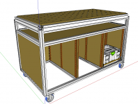
Been planning this a long time, I actually started 2 of these and the dimensions were not right, actually just not well thought out. The goal is to have one cart combining the best of the MFT, a slightly larger top at my preferred 37" working height, and incorporating systainer storage. After messing up the first attempts I decided it needed to be drawn to exact dimensions before I started chopping up more 80/20. This is the result so far:

[attachthumb=1]

[attachthumb=2]

[attachthumb=3]

[attachthumb=4]

Overall width is ~55" and depth is 32".

I am using 28" long full-extension drawer slides so I will have room for 2 systainers deep, 2  sets high, or 12 total. Any excess space above the systainers will get shallow full depth (28") drawers, ideal for holding the Rip Guides, dogs, clamps, etc. The shelf under the MFT top will be perfect to store all the big red squares and straight edges.

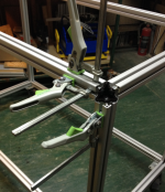
All the panels  will be MDF of birch ply, with rabbeted tongues (with the exception of the top) to fit into the slots on the extrusions. Most of the 80/20 will be put together with the inexpensive standard end fasteners (no brackets), with the exception of the 1530 around the top which will get some extra brackets to stiffen it up.

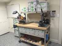
Depending on how the spirit moves me this weekend I may postpone finishing the shop walls and start on this, when it is done it will sort out a lot of the clutter in the shop.

Suggestions for any improvements are welcome.

RMW
 

Attachments

  • ScreenClip.png
    ScreenClip.png
    115.7 KB · Views: 6,012
  • ScreenClip [1].png
    ScreenClip [1].png
    93.3 KB · Views: 2,789
  • ScreenClip [2].png
    ScreenClip [2].png
    119.5 KB · Views: 2,894
  • ScreenClip [3].png
    ScreenClip [3].png
    48.4 KB · Views: 2,506
Richard

I like the design.  Looks like it will give you a lot of storage plus some good strength.  80/20 is really great stuff.  I drew my drawing in Sketchup like you and then sent it to the 80/20 rep for his refinements and quoting.  Worked great to go back and forth that way.

Here's an 80/20 bench I made for Systainers and other items.  Might give you some ideas.

- The upper shelf uses 80/20 back rails with extra standoffs to extend around the overlay top.  I like having the upper shelf so I don't have to bend down for every item.  Most of the overhead Systainers actually go to a destination - like router bits to the CMS or the Vecturo being used away from the shop.
- The sortainers have a strip across the back to hold them in place and keep them from sliding.  There is space behind them for seldom used tools.
- I did a vise on the end with the top offset to provide clearance and the wheels lock giving me a very sturdy bench
- Bottom shelf is for 'future purchases'
- I got the heavy maple top at Woodcraft.  I have a couple of other tables drilled for 20mm holes and clamping
- The plywood shelves were finished with acrylic poly and dropped in place to fit between the posts during assembly.  Looks like you are capturing yours in the 80/20 rails.  I wanted mine to allow full access rather than having the rail extend above them, reducing access from the edge.  They are all screwed down to T-nuts captured in the 80/20
- You can't see it but I captured a power strip on the side rails on the left side with T-Nuts for easy power.

[attachimg=#]

I debated doing pull out shelves but I have the full Systainer port to the left and several other pull out storage units in the shop.

Might give you some ideas.

Neil
 

Attachments

  • IMG_0765.JPG
    IMG_0765.JPG
    2.1 MB · Views: 15,157
Thanks Neil. I like the upper shelf, have to give that some thought.

Also like the vise on the overhang, my old traditional maple bench had one & it was used a lot. This thing should easily weight 3-400# when it is loaded, so it should be stable enough for hand planing, so the vise would be nice to ahve.

I see a few steppers on the shelf, are you dabbling in CNC?

RMW
 
On your question on stepper motors, yes - I have a small mill and a lathe and am in the process of converting them to CNC.  Also working on an Arduino controlled fence for the CMS with a stepper, screw drive, pillow blocks with bearings, and a couple of rails.  Should be under $100 in parts and a little time.

I have a friend with a full machine shop - Bridgeport, Hardinge Lathe and Tormach.  Awesome machines.  Love the manual machines and slowly learning the CNC stuff. 

I have the bug but don't have the space or budget!

neil
 
[member=167]neilc[/member]

I'm already getting the thread off-topic but I'm kinda infatuated with CNC myself. I have small HandiBot router mill for making jig parts, & was playing with some Arduino boards and steppers this winter to pass the long nights, once the shop is back in working order I am going to rig up some linear motion goodies myself.

Check out the new V-Slot linear actuator kits, $150 gets you the 1,000 mm extrusion, all the linear motion parts and a NEMA 23:

http://openbuildspartstore.com/c-beam-linear-actuator-bundle/

The inventors, Mark and Trish are simply brilliant makers and have come up with a great modular 20mm system for linear motion.

RMW
 
Richard - that's awesome!  I'll definitely explore that site more.

When I start down the build of the arduino controlled fence, I'll start a thread here.

neil
 
Richard from the plan it looks like you have 2 upright frame pieces of 80/20 in the back of the piece. Are those needed? It would seem that making the back piece one solid unit with perhaps a dado or dominoes to join the sided where the drawers go might make construction easier and the whole piece more rigid.

On the pieces of 80/20 where the t slot is captured (like the long horizontals) could you mill the slot a bit larger in an area so you could drop in a clamp and then slide it over?

I realize that it could compromise the extrusion perhaps, but I don't think you'd need to open it up a lot. Plus you also have a lot of support built into those pieces with the sides, top and drawer divider sections.

Ron
 
rvieceli said:
Richard from the plan it looks like you have 2 upright frame pieces of 80/20 in the back of the piece. Are those needed? It would seem that making the back piece one solid unit with perhaps a dado or dominoes to join the sided where the drawers go might make construction easier and the whole piece more rigid.

On the pieces of 80/20 where the t slot is captured (like the long horizontals) could you mill the slot a bit larger in an area so you could drop in a clamp and then slide it over?

I realize that it could compromise the extrusion perhaps, but I don't think you'd need to open it up a lot. Plus you also have a lot of support built into those pieces with the sides, top and drawer divider sections.

Ron

Ron,

I was tossed on the rear panel dividers, finally went with them for 2 reasons, they replace fasteners in the rear panel/center panel connection and by breaking up the rear panel I get better use of 4 by 8 sheets. Also I have a ton of 80/20 so it was no big expense.

Regarding getting clamps in the slots, I will probably do what you suggest but there is only one slot (bottom one on the 1530) that is not accessible. When I was building the first version I modified some corner brackets to open up each slot which is why the corner posts stop short of the top of the 1530 - this is what it looks like on the second version before the brackets are added:

[attachthumb=1]

This was the fist version with the corner brackets in place:

[attachthumb=2]

Thanks for the suggestions.

RMW


Attachments

  • ScreenClip.png
    ScreenClip.png
    1.1 MB · Views: 9,012
  • ScreenClip [1].png
    ScreenClip [1].png
    227.9 KB · Views: 9,571
Richard,

  Do you CNC the tops yourself or do know someone down by you that does it for you? I am in the planning stage of building one 72" X 32".

- Rich
 
That looks similar to the one that I built recently.  One thing that I did, that you might consider, is I divided the top into 3 sections with two crosspieces.  Then I made basically mini-versions of the Paulk bench that drop into the holes.  That allows me to pull them out and replace them if they get damaged and eliminates the lower horozontal piece of 80/20.  It also allows me to make different modules that can drop into the sections as needed- a router module, sanding module etc.  Anyway, I'm not quite finished with it, but it seems to be working well.
 
Richard A. said:
Richard,

  Do you CNC the tops yourself or do know someone down by you that does it for you? I am in the planning stage of building one 72" X 32".

- Rich

Rich, I have not made the top yet and am still undecided. There is a shop in EHT that has a 5 by 10 shopbot, they quoted me $100 for a full sheet if I supply the material.

I have a method thought out using the LR32, and there are several threads on this subject, so I may try it myself first.

Check out www.100kgarages.com to locate CNC machine owners near you.

RMW
 
Ron, forgot about that extrusion.

I use the Bessey auto adjusts a lot with 80/20, all they need is a 5/8 ish hole for the head of the 5/16 screw to go thru. I may limit myself to those clamps in the slots that are blocked.

RMW
 
Dane said:
That looks similar to the one that I built recently.  One thing that I did, that you might consider, is I divided the top into 3 sections with two crosspieces.  Then I made basically mini-versions of the Paulk bench that drop into the holes.  That allows me to pull them out and replace them if they get damaged and eliminates the lower horozontal piece of 80/20.  It also allows me to make different modules that can drop into the sections as needed- a router module, sanding module etc.  Anyway, I'm not quite finished with it, but it seems to be working well.

Dane thanks for the suggestion. I had considered that before and forgot about it.

I like that idea because I can use the Bessey clamps in those extrusions also.

Post some photos of your bench if you have them.

RMW
 
Geeze this "making accurate plans for stuff before building it" BS is tough work! I've been tweaking the SketchUp plan in my spare time for the past week, all the while fighting with the finer points of using SU Pro/Layout. I think I'm finally gaining on it...

The learning experience has been how to think thru all the measurements. For example I started with a 96mm grid of holes on the MFT top, with a 64mm outside border (from CL of the last hole) then tried to make the inside dimensions work out - end up with extrusions I needed to cut in really odd lengths. Too simple to screw up in the shop.

I got hung up on trying to make things in 32MM increments, further messing up my head. Finally figured out to focus on the things that needed to be a certain dimension, i.e:

  • Minimum shelf width for a Systainer + drawer slide width *3 + 2 divider panels = minimum MFT top width
  • Length of drawer slides = minimum MFT top depth
  • Take minimum top width, divide by 96 then round down to even number *96 + outside margin to get actual MFT top target width
  • Take top target width, subtract divider panel thickness, divide by 3 to get individual Systainer bay widths, check that against minimum Systainer shelf width needed
  • Lather, rinse, repeat...

I have a new-found respect for guys who develop plans and sell them, it's a boatload of work. Anyway, here's the latest:

Perspective w/ 2X Sys-2

[attachthumb=1]

Example front view with measurements

[attachthumb=2]

Now that I have all the views I need to take it all out into the shop and check the measurements to see where the plans diverge from reality...

RMW


Attachments

  • ScreenClip [3].png
    ScreenClip [3].png
    122.4 KB · Views: 4,583
  • ScreenClip [4].png
    ScreenClip [4].png
    59.9 KB · Views: 3,092
Richard,

  In your new dimensional front view it looks like you have the top rail mounted too low. I thought the whole idea was to have the top groove of the top rail higher than the sides so you could slide clamps in from the sides.

- Rich
 
Richard A. said:
Richard,

  In your new dimensional front view it looks like you have the top rail mounted too low. I thought the whole idea was to have the top groove of the top rail higher than the sides so you could slide clamps in from the sides.

- Rich

Rich,

It must not be showing clearly in the drawing, the top extrusion is 3" high, the side extrusion only come up 1.5" on it, leaving the top & upper side slots open.

There is a photo earlier in the thread of V2.0, same setup. Each top/side slot is clear:

[attachthumb=1]

RMW

RMW
 

Attachments

  • ScreenClip [5].png
    ScreenClip [5].png
    39.2 KB · Views: 4,766
Richard,

  In looking at it again, I see it now. It must have been an optical dillusion. I saw it in your original design but at first glance, on your new front view, I thought you changed it. When I first saw your 3" top rail with your 1- 1/2" side posts, I thought that was the greatest thing about your whole design. (& why didn't I think of it. lol)

  By the way, I found a CNC shop in my area from the link you told me about. Thanks again.

- Rich
 
Richard A. said:
Richard,

  In looking at it again, I see it now. It must have been an optical dillusion. I saw it in your original design but at first glance, on your new front view, I thought you changed it. When I first saw your 3" top rail with your 1- 1/2" side posts, I thought that was the greatest thing about your whole design. (& why didn't I think of it. lol)

  By the way, I found a CNC shop in my area from the link you told me about. Thanks again.

- Rich

Cool. Not sure where you are in Jersey but, in case you did not see it, there is a ShopBot "Camp" down here in May:

http://festoolownersgroup.com/member-connections/s-new-jersey-camp-shopbot-516-in-mays-landing/msg386986/#msg386986

RMW
 
Back
Top