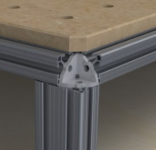
(Yet another) 80/20 MFT/SYS Cart

Hello [member=41421]Peter[/member]

Thanks for sharing this option. Looking forward to your review video and opinion.

Ocram

Peter Parfitt said:
Ocram said:
It looks very nice Richard. I got a question for you, can explain to me how the guide fence from the MFT is attached to the dogs? Or even better cap you post a closeup picture?

Greets Ocram

Hi [member=8584]Ocram[/member]

I am in the middle of making a new video with some updates on the Parf Guide System and so on. One thing that I do mention are the UJK Guide Rail Clips for the Parf (or any other 20 mm) dogs. They are available from Axminster. Here is a link:
http://www.axminster.co.uk/ujk-technology-dog-rail-clip-pair-102973

They have been designed by Axminster, I have nothing to do with them at all but I have used them and they work brilliantly.

Peter
 
I scored this nice workbench, secondhand, apparently originally used at a local university in their science labs:

Xplvs6fSHdqzSo5u1oKdVV0br75g4HxfWOJC9OJt3V5ZyMNNluCRrr3ToP00aYbC-JlCnbbwiCL00BUUPZhV0SQa8vr1mqW56zirkI1NI3cecsG96bb1_B9xJy-jR_1qH2N26fO6MncSF1pf44MoRkeNhCWx83Rud37f6KbF7Z5hoRNIRM7qc8I1L63qaG97TkMTDfMddKjGdkC3hMoZC9lqBzMOt_VixA0lM3VxcJtgqOkfcTe6gXyFDJnd_Gsz66qkD88chTa_NshtvFCK5lbsTvR5mOWB4emQINr6Kx64rYhWLFEQSIL6lYtU4YsgCyXpvKMPNJbgaxxAf8NhKHiqedcPWCEH0iTEWlaalhKpVi2g9xKGpJ8B_Tx9YGDS-vzeiR571t6cM4I_EjzUoSk_PXvdFOm5472TpiFOeIuq7qZAKZGUNLZg3hMLR5YUhq0g6YEKP_aRBkjUQQDjkpTzLJc_r0DGziAgtVipvKW6aD37Y3JLbAaVHDuVRBNT9VmXS5op_69ru0ujxSds5VrQM43-E8Zx1zzQVjbsVOb9sTcX-YQF1mCciVFaX6YSG-p1GCQEBrs_rxdta7MI84Tofog_l1DF6d3pC7UuFluO8N8A43VX=w1000-h591-no


I only realized after the fact that it has about $1,000 worth of 80/20 extrusions and fasteners, including two really nice and super heavy duty pull-out drawers.

While this design could (and has been) working as a makeshift JumboMFT, I've wanted to make a few design improvements for some time. And, of course, the great thing about 80/20 is that it can be broken down and re-assembled with minimal effort. Here was my list of design improvements, in order of importance:

1) Provide a means to open up the extrusions along the top, for clamping access. These extrusions are 15 Series, so I believe Festool clamps will slide right in without issue. The dilemma here is that the clamping channels are enclosed, so a new fastening method would have to be employed.

2) Provide an open "top deck" where random trinkets could be stored. This deck would ideally run underneath the entire working surface, and yet provide enough headroom for the Festool clamps to slide in without issue.

3) Enclose the bottom portion of the cabinet, to keep out dust and debris.

4) Make it mobile. Even though the rubber feet shown above are incredibly grippy (called Mighty Mounts, and a whopping $50 apiece), I would appreciate the workbench being mobile. However, I still want stability, so I'm planning to use double-locking casters (locking both the wheel and swivel articulation). There will be some loss of stability, but the mobility trade-off is worth it to me.

5. Add miter gauge channels along the left-hand side of the surface. This workbench will do double-duty as an outfeed table for my Powermatic 65 tablesaw. Another project in the queue is to build a mobile base for that tablesaw, and at that time, I'll make sure to provide a means to level it such that it will be flat with this working surface.

I've been able to incorporate most of these improvements in the design below. I took careful measurements and re-created the workbench in a parametric modeling program. This is just a rendering, not yet reality, but I think it can be overhauled at a cost of about $150 in 80/20 components, casters, and plywood.

9cNjckflBiq96Lm8UfEVUgyU8pkNiDvQ0TzNt6raVH_ykDij6ZjcjMMnpk1ev-4pUdJHUPXDfTypMH_rphUraIT_jeh5Tp3xkT24qZ4KkNsJdDp-GcB4gfZw2E6ur4FcJ2bS0QMMS8lF9grT_8zxs0tKOPCO7qQxqpmSSepJVMjfKECjXYTQZrkNUit1ZWd1m0qjZ4yiu6Ix4oHOVe5GKkISF644lw-GRVLWcl1RgaJHSIJx9xmpimQJvjXWek2syr-362DirlsFUwJ49oeaVFi-eyudvXMP3hC6jwe7g6p1GIRC1oY5m5Wev4NUFWjwcVRDBcmwm1LvRpv71vJ1icHGdCAgJnZdmOm5PL6veA-PxATArv_z65Bat6GE9ke5BLqKd5ZLGFsUkTgQlmmy3-vIXSKQt4UZOfclMNE8hpZ_M7pZuqKIUN2oFDUZ3L0HHs6uK6vk0Gi9FcD-8Xewa03HprabBZxE4OCwxJzaD-3GLU8R632D4FlPdVJopfpXqhRT69yg6VNIsV4S-6NxQUE6YL8FfWQ68oiDpahsQy49EtMgL4IIxUh31OCo1Zih-0cm6XPjT-PMBi0LbwJIo_m6aGjQE474b5Gytlz6fxKP7UPv6MM2=w1797-h1261-no


PJ9-JwzxLe2cdGSWSGxU7OURjLNg03Rkrh27Qmqn1mGDMTQjb12x_j7drq332LXKrlCQe8rNWUX9lyej2IeN3YfQ55MWIZala096XsATz3_OmItv2ya588Wj6AL-6q3zU1TqNSvllIkmApj36hBIfSZD068JjyRfubbuiycBjcDmaOcR1qRwowNnar7pPGUfAEFbQYv1k0NssR7t_zrhY_ey_rD2wgpyk4hwt0AoW88S1BiOk_QeUfm7Mo3YnffLzYy5Pl9K4L_jhI6lakvm2MNShreDlosB-YtLN8fBdYDIg7tYLClFtVT9N23U0f2emf1Wky5NHZDZR_r4qbD13p57fGynEsslqCXOyzsR9fGZ4MLQQMihL7IcF1XIz__cgFt3MW57YymH1pRZ2BaW4MELo9laxK6uC5oFjvnJz3epIbtWQQlMgb6SchvT9zrvflrxiA27Jer54cayVHnk39FKUiLYhkmAytapU7nKHOTh4AqS3QhkrtyPIiAakwwH2H0s7BjvInytoVb3qXVaMV2MvSOyp5agTm1X1a7Y6SZCucKp91GQtwCEYH661SPNIwPADsC1pZyX8SvaGHDeac8i-Ttoe2gda8VPMby1XqQvWUBnKy2i=w2308-h1261-no


-PIZYMY-rLf5xVdC1RJS1q76EcfhbGY4L0YsyMow8NdUmFOY2jza5S8POYaRrf-7vFgxbnhE7XCNiyYtGgRsY_s-TxXfXr4ufAHZzodwSSZoDWvFnrvwMo7oJRfKBRYRbpW7JjT-ISd05Q0H5OrWJ6k2ODtZvHWy78DxRRhuJ_YRmAd1c_DbxUR8F0nKVeun4YbsIxQwffKHa1Uv-6L0-zqLnXHLfj8S0TxmXREbusbtUYMsBHGt8W5bCqydH7TlarEBQa33p8ucLjVljD-eqMbFBm36ZmCG5y8J9U-7R3pxL5VFmeuZsRNij_lfkOcBUgHBGMbwk8XbRlUswEPhuwJsFKvgtWH3xt7QkKWvAG0vgGhvJU2FmEx3-9Tkj5CZjdut9uXHsWhADBkH1FKJbJsrj4cl2v6a49BYIWAIt5Ei0bdJ3n3VSVtOlhjruQEkrLiY_7sI9wkc_ip-plMKFsZ8zbl7ivQlUwKKw5U8uW8yedF855LbhBlt-3-JvZ0y47KfGHI6Jyd_fuhAPsAUME_P_Ds7VgERXANv6kgtYZxMrrB67GjPGBpiFS5tMvLUqQw8S7885eq3hisnJCntum4nFxKOTMqxNsOBbCQysTEC5mvyv4Th=w1395-h1261-no


P0g7BA6_Ag1V7R_l7Ptnmg8HPLsiG4L87vmiJd67nDVDq3kXoujUxXJbNeXPYpRHgLkBCw4pYujnP0v_rODMe6mBTSd18OEpmkcBdKU5isiJMnWOcTh1Drvb0MvP4UOgP4MY_H7LhCwUR6OolMe2HLZVMxNUaGx68GTIeyVOPKv7mFwSITFCQO1Q7vzZWYlRrmd5-d5Irexvs53S2z7mAO1JPkSMYIi4RuracYO_OGw8tDPhu8o-h0I1azMF7Ovf6SGckgck3NHk3csIxmEw2gSNJ8oZIuejitm0PRfzu46g0_wezTpGwdlfcBf7jAj9lMO1shQ7AKxPFr01D5W-tOhuVpz7qc9JJlHK7MxWDQmJf89-5OqlyufFnizM4hdQ7AmcUKj6PDpVZuvXPBlna3tX24LKGZbWLUTAVpJn31oHho1_qnp-HY0V2Yh8dig6vKay5edxmTBq40kypVBtMdKZ3kgjjoEILx9QdfpUh6BeArexDI4SuM4G1fii7hepZ8oM5Qc7AvHW2aR-ptaUqKTCZh64Mowz_8WoT7-xz4JxJb9IS1XpKAuFTTD3H8MSAavzrrX1PZjNj1JDEqC_hXyTdbYfMwK4Bn8tYuFAs33rrSEx8rZQ=w2500-h1062-no


Let me know what you think!
 
Hello [member=51886]ryanjg117[/member] , very nice en looks solid too. Your plans for converting it in a jumbo MFT would be my idea too.

If you want to put a vac in the bench I personally find it handy too store it on the right side of the bench since I am right handed. I wold put right drawer in the middle to create space for the vac.

What ever you do, it will be a killer bench.

Greeting Ocram
 
[member=51886]ryanjg117[/member] Nice score getting the used bench. Looks like they used linear bearings for the drawer slides, total overkill but I guess budget wasn't a concern for them. You might consider salvaging them for later use in something else and replace with cheap 100# full extension slides. You would also have all the extrusions to re-purpose since you are adding an end panel that the slides can mount to.

FWIW you will need to trim the corner brackets to get the Festool clamps into the t-slots, They partly block the slot:

[attachimg=1]

Hopefully you can see how these are trimmed from this photo:

[attachimg=2]

If you are shopping for casters check out castercity.com - you can mix/match wheels/brakes/mounts and get nice 4" casters for around $15 with the double locking brake. I'm a fan of these.

Going to be a great bench when you are done with it.

RMW

ryanjg117 said:
I scored this nice workbench, secondhand, apparently originally used at a local university in their science labs:

Xplvs6fSHdqzSo5u1oKdVV0br75g4HxfWOJC9OJt3V5ZyMNNluCRrr3ToP00aYbC-JlCnbbwiCL00BUUPZhV0SQa8vr1mqW56zirkI1NI3cecsG96bb1_B9xJy-jR_1qH2N26fO6MncSF1pf44MoRkeNhCWx83Rud37f6KbF7Z5hoRNIRM7qc8I1L63qaG97TkMTDfMddKjGdkC3hMoZC9lqBzMOt_VixA0lM3VxcJtgqOkfcTe6gXyFDJnd_Gsz66qkD88chTa_NshtvFCK5lbsTvR5mOWB4emQINr6Kx64rYhWLFEQSIL6lYtU4YsgCyXpvKMPNJbgaxxAf8NhKHiqedcPWCEH0iTEWlaalhKpVi2g9xKGpJ8B_Tx9YGDS-vzeiR571t6cM4I_EjzUoSk_PXvdFOm5472TpiFOeIuq7qZAKZGUNLZg3hMLR5YUhq0g6YEKP_aRBkjUQQDjkpTzLJc_r0DGziAgtVipvKW6aD37Y3JLbAaVHDuVRBNT9VmXS5op_69ru0ujxSds5VrQM43-E8Zx1zzQVjbsVOb9sTcX-YQF1mCciVFaX6YSG-p1GCQEBrs_rxdta7MI84Tofog_l1DF6d3pC7UuFluO8N8A43VX=w1000-h591-no


I only realized after the fact that it has about $1,000 worth of 80/20 extrusions and fasteners, including two really nice and super heavy duty pull-out drawers.

While this design could (and has been) working as a makeshift JumboMFT, I've wanted to make a few design improvements for some time. And, of course, the great thing about 80/20 is that it can be broken down and re-assembled with minimal effort. Here was my list of design improvements, in order of importance:

1) Provide a means to open up the extrusions along the top, for clamping access. These extrusions are 15 Series, so I believe Festool clamps will slide right in without issue. The dilemma here is that the clamping channels are enclosed, so a new fastening method would have to be employed.

2) Provide an open "top deck" where random trinkets could be stored. This deck would ideally run underneath the entire working surface, and yet provide enough headroom for the Festool clamps to slide in without issue.

3) Enclose the bottom portion of the cabinet, to keep out dust and debris.

4) Make it mobile. Even though the rubber feet shown above are incredibly grippy (called Mighty Mounts, and a whopping $50 apiece), I would appreciate the workbench being mobile. However, I still want stability, so I'm planning to use double-locking casters (locking both the wheel and swivel articulation). There will be some loss of stability, but the mobility trade-off is worth it to me.

5. Add miter gauge channels along the left-hand side of the surface. This workbench will do double-duty as an outfeed table for my Powermatic 65 tablesaw. Another project in the queue is to build a mobile base for that tablesaw, and at that time, I'll make sure to provide a means to level it such that it will be flat with this working surface.

I've been able to incorporate most of these improvements in the design below. I took careful measurements and re-created the workbench in a parametric modeling program. This is just a rendering, not yet reality, but I think it can be overhauled at a cost of about $150 in 80/20 components, casters, and plywood.

9cNjckflBiq96Lm8UfEVUgyU8pkNiDvQ0TzNt6raVH_ykDij6ZjcjMMnpk1ev-4pUdJHUPXDfTypMH_rphUraIT_jeh5Tp3xkT24qZ4KkNsJdDp-GcB4gfZw2E6ur4FcJ2bS0QMMS8lF9grT_8zxs0tKOPCO7qQxqpmSSepJVMjfKECjXYTQZrkNUit1ZWd1m0qjZ4yiu6Ix4oHOVe5GKkISF644lw-GRVLWcl1RgaJHSIJx9xmpimQJvjXWek2syr-362DirlsFUwJ49oeaVFi-eyudvXMP3hC6jwe7g6p1GIRC1oY5m5Wev4NUFWjwcVRDBcmwm1LvRpv71vJ1icHGdCAgJnZdmOm5PL6veA-PxATArv_z65Bat6GE9ke5BLqKd5ZLGFsUkTgQlmmy3-vIXSKQt4UZOfclMNE8hpZ_M7pZuqKIUN2oFDUZ3L0HHs6uK6vk0Gi9FcD-8Xewa03HprabBZxE4OCwxJzaD-3GLU8R632D4FlPdVJopfpXqhRT69yg6VNIsV4S-6NxQUE6YL8FfWQ68oiDpahsQy49EtMgL4IIxUh31OCo1Zih-0cm6XPjT-PMBi0LbwJIo_m6aGjQE474b5Gytlz6fxKP7UPv6MM2=w1797-h1261-no


PJ9-JwzxLe2cdGSWSGxU7OURjLNg03Rkrh27Qmqn1mGDMTQjb12x_j7drq332LXKrlCQe8rNWUX9lyej2IeN3YfQ55MWIZala096XsATz3_OmItv2ya588Wj6AL-6q3zU1TqNSvllIkmApj36hBIfSZD068JjyRfubbuiycBjcDmaOcR1qRwowNnar7pPGUfAEFbQYv1k0NssR7t_zrhY_ey_rD2wgpyk4hwt0AoW88S1BiOk_QeUfm7Mo3YnffLzYy5Pl9K4L_jhI6lakvm2MNShreDlosB-YtLN8fBdYDIg7tYLClFtVT9N23U0f2emf1Wky5NHZDZR_r4qbD13p57fGynEsslqCXOyzsR9fGZ4MLQQMihL7IcF1XIz__cgFt3MW57YymH1pRZ2BaW4MELo9laxK6uC5oFjvnJz3epIbtWQQlMgb6SchvT9zrvflrxiA27Jer54cayVHnk39FKUiLYhkmAytapU7nKHOTh4AqS3QhkrtyPIiAakwwH2H0s7BjvInytoVb3qXVaMV2MvSOyp5agTm1X1a7Y6SZCucKp91GQtwCEYH661SPNIwPADsC1pZyX8SvaGHDeac8i-Ttoe2gda8VPMby1XqQvWUBnKy2i=w2308-h1261-no


-PIZYMY-rLf5xVdC1RJS1q76EcfhbGY4L0YsyMow8NdUmFOY2jza5S8POYaRrf-7vFgxbnhE7XCNiyYtGgRsY_s-TxXfXr4ufAHZzodwSSZoDWvFnrvwMo7oJRfKBRYRbpW7JjT-ISd05Q0H5OrWJ6k2ODtZvHWy78DxRRhuJ_YRmAd1c_DbxUR8F0nKVeun4YbsIxQwffKHa1Uv-6L0-zqLnXHLfj8S0TxmXREbusbtUYMsBHGt8W5bCqydH7TlarEBQa33p8ucLjVljD-eqMbFBm36ZmCG5y8J9U-7R3pxL5VFmeuZsRNij_lfkOcBUgHBGMbwk8XbRlUswEPhuwJsFKvgtWH3xt7QkKWvAG0vgGhvJU2FmEx3-9Tkj5CZjdut9uXHsWhADBkH1FKJbJsrj4cl2v6a49BYIWAIt5Ei0bdJ3n3VSVtOlhjruQEkrLiY_7sI9wkc_ip-plMKFsZ8zbl7ivQlUwKKw5U8uW8yedF855LbhBlt-3-JvZ0y47KfGHI6Jyd_fuhAPsAUME_P_Ds7VgERXANv6kgtYZxMrrB67GjPGBpiFS5tMvLUqQw8S7885eq3hisnJCntum4nFxKOTMqxNsOBbCQysTEC5mvyv4Th=w1395-h1261-no


P0g7BA6_Ag1V7R_l7Ptnmg8HPLsiG4L87vmiJd67nDVDq3kXoujUxXJbNeXPYpRHgLkBCw4pYujnP0v_rODMe6mBTSd18OEpmkcBdKU5isiJMnWOcTh1Drvb0MvP4UOgP4MY_H7LhCwUR6OolMe2HLZVMxNUaGx68GTIeyVOPKv7mFwSITFCQO1Q7vzZWYlRrmd5-d5Irexvs53S2z7mAO1JPkSMYIi4RuracYO_OGw8tDPhu8o-h0I1azMF7Ovf6SGckgck3NHk3csIxmEw2gSNJ8oZIuejitm0PRfzu46g0_wezTpGwdlfcBf7jAj9lMO1shQ7AKxPFr01D5W-tOhuVpz7qc9JJlHK7MxWDQmJf89-5OqlyufFnizM4hdQ7AmcUKj6PDpVZuvXPBlna3tX24LKGZbWLUTAVpJn31oHho1_qnp-HY0V2Yh8dig6vKay5edxmTBq40kypVBtMdKZ3kgjjoEILx9QdfpUh6BeArexDI4SuM4G1fii7hepZ8oM5Qc7AvHW2aR-ptaUqKTCZh64Mowz_8WoT7-xz4JxJb9IS1XpKAuFTTD3H8MSAavzrrX1PZjNj1JDEqC_hXyTdbYfMwK4Bn8tYuFAs33rrSEx8rZQ=w2500-h1062-no


Let me know what you think!
 

Attachments

  • ScreenClip (Small).png
    ScreenClip (Small).png
    155.7 KB · Views: 16,203
  • ScreenClip [1] (Small).png
    ScreenClip [1] (Small).png
    422.4 KB · Views: 15,434
Richard/RMW said:
You might consider salvaging them for later use in something else and replace with cheap 100# full extension slides. You would also have all the extrusions to re-purpose since you are adding an end panel that the slides can mount to.

FWIW you will need to trim the corner brackets to get the Festool clamps into the t-slots, They partly block the slot:

Richard, thanks for the info on the issue with the corner brackets... I was a little worried those might not be open enough, so I'll have to be sure to bore those out before attempting to put it all together. Also, good idea on pulling out and potentially repurposing the linear bearings for a future project. They really don't make all that great a drawer slide because they take a lot of force to actuate--nothing like the smooth Blums I'm used to. Speaking of which, I've got a few Blum drawer slide kits sitting around... Might be a good use for this.

Funny you mention the same source for casters that I've been eyeing for this project. I'm a big fan of the "total locking" casters and will probably go with four of the 3" 300-pound rated casters for this project.

 
[member=51886]ryanjg117[/member] - I'll see if I can locate photos of the mod necessary on the corner bracket, although I am sure it's not hard for you to envision. I put the cap screw in and traced it's outline, then struck a line from corner to corner with a straightedge and removed everything outside the lines.

FWIW, if you decide to go with standard glides, after some trial/error I concluded that the best end panel is made up of 2 pieces of 1/2" laminated then you route a dado leaving an 8mm (5/16") tongue to slip into the slot. With the 15 series profile this leaves the inside face of the panel a couple MM proud of the extrusion and it's simple to mound the glides. These photos show what I am referring to.

Have fun!

RMW

ryanjg117 said:
Richard/RMW said:
You might consider salvaging them for later use in something else and replace with cheap 100# full extension slides. You would also have all the extrusions to re-purpose since you are adding an end panel that the slides can mount to.

FWIW you will need to trim the corner brackets to get the Festool clamps into the t-slots, They partly block the slot:

Richard, thanks for the info on the issue with the corner brackets... I was a little worried those might not be open enough, so I'll have to be sure to bore those out before attempting to put it all together. Also, good idea on pulling out and potentially repurposing the linear bearings for a future project. They really don't make all that great a drawer slide because they take a lot of force to actuate--nothing like the smooth Blums I'm used to. Speaking of which, I've got a few Blum drawer slide kits sitting around... Might be a good use for this.

Funny you mention the same source for casters that I've been eyeing for this project. I'm a big fan of the "total locking" casters and will probably go with four of the 3" 300-pound rated casters for this project.
 
[member=8712]Richard/RMW[/member] My New Year's resolution for 2017 is to finally build the 80/20 MFT Outfeed Table I've been planning since you started this thread!

I have a couple of questions that I am hoping you will answer for me.

I love the folding side table and was wondering about getting the right parts for the hinges so that it can fold down out of the way as well as lock in the upright position.  Can you elaborate?

Also, you may have already explained this but what process do you use for threading the 80/20 yourself?

Many thanks!

Joe
 
[member=6237]deepcreek[/member] - Howdy Joe. If you are planning on making a flip-up outfeed table this setup should work great. The supports are KV 0206.

Video of power tapping the 80/20:


I only use the Ultra-Light Smooth (1515 ULS) profiles, in which the end holes have an "X" shaped relief that reduces the surface area of the hole itself and tapping with a drill works fine. If you used the heavier 1515 profile the hole is solid and the only time I ever broke a tap was in that extrusion. It is also overkill, the ULS works for everything I have done. 

Other than tapping the ends you need to drill an access hole inside the slot to reach thru and tighten the fasteners, unless you are only using corner brackets. You can either drill the holes on a drill press or 80/20 sells a drill guide for around $30.

Clear as mud?

RMW

deepcreek said:
[member=8712]Richard/RMW[/member] My New Year's resolution for 2017 is to finally build the 80/20 MFT Outfeed Table I've been planning since you started this thread!

I have a couple of questions that I am hoping you will answer for me.

I love the folding side table and was wondering about getting the right parts for the hinges so that it can fold down out of the way as well as lock in the upright position.  Can you elaborate?

Also, you may have already explained this but what process do you use for threading the 80/20 yourself?

Many thanks!

Joe
 
[member=8712]Richard/RMW[/member]

Thank you so much!

That video was very encouraging.  As simple as using a little cutting oil and a tap in a cordless drill. 

Before seeing it, I was trying to figure out how to get long lengths under my bench top drill press!

Any tips on accurately cutting the pieces to length?

Joe
 
Richard will be able to provide a lot more advise, but I have cut 80/20 using my sliding miter saw.  I use high tooth blade, lock slide and cut very slow.
 
Joe, I use a dedicated metal cutting chop saw with an AL blade. As Bryan stated I think you can make the same cut with most any SCMS using the right blade. For reference my 14" Milwaukee dry-cut saw is 1,500 RPM, and the Oshlun blade cuts thru it like butter. I've never used any lube, & again as Bryan stated just cut slowly and let the blade do it's job.

RMW

PS - love your designs/creations.  [not worthy]


Richard/RMW said:
Joe, I use a dedicated metal cutting chop saw with an AL blade. As Bryan stated I think you can make the same cut with most any SCMS using the right blade. For reference my 14" Milwaukee dry-cut saw is 1,500 RPM, and the Oshlun blade cuts thru it like butter. I've never used any lube, & again as Bryan stated just cut slowly and let the blade do it's job.

I have a 14" Dewalt metal chop saw and found that Olshun blade on Amazon along with a 12" version that will fit my old reliable Dewalt 705 miter saw.  (I kept it for cuts I don't want to make on my Kapex.) Now I just have to decide which one will work better!!??

One last question (I think) - What tool did you use to trim the excess profile of the corner brackets?

Richard/RMW said:
PS - love your designs/creations.  [not worthy]

Thanks for the kind words.  I love your designs/creations!
 
Wooden Skye said:
Richard will be able to provide a lot more advise, but I have cut 80/20 using my sliding miter saw.  I use high tooth blade, lock slide and cut very slow.

Thanks, Bryan!
 
Portaband mounted in table top setup and a Foredom with carbide burr for cleanup. Those brackets are cast so you can probably get away with a hacksaw and files if need be.

Post pics when you get it done.

RMW

deepcreek said:
Richard/RMW said:
Joe, I use a dedicated metal cutting chop saw with an AL blade. As Bryan stated I think you can make the same cut with most any SCMS using the right blade. For reference my 14" Milwaukee dry-cut saw is 1,500 RPM, and the Oshlun blade cuts thru it like butter. I've never used any lube, & again as Bryan stated just cut slowly and let the blade do it's job.

I have a 14" Dewalt metal chop saw and found that Olshun blade on Amazon along with a 12" version that will fit my old reliable Dewalt 705 miter saw.  (I kept it for cuts I don't want to make on my Kapex.) Now I just have to decide which one will work better!!??

One last question (I think) - What tool did you use to trim the excess profile of the corner brackets?

Richard/RMW said:
PS - love your designs/creations.  [not worthy]

Thanks for the kind words.  I love your designs/creations!
 
Great projet and thread! Any tips/pointers on the best place to purchase these extrusions and connectors?
Thanks,.
 
Howdy [member=63160]mindbend[/member]  [welcome] to the FOG.

I get my stuff from 80/20's eBay store.

RMW

mindbend said:
Great projet and thread! Any tips/pointers on the best place to purchase these extrusions and connectors?
Thanks,.
 
Got it! Thanks.

p.s. I've made some corner connectors via my 3D printer that don't need to be hacked/cut. May be advantageous for builders here.
 
mindbend said:
Got it! Thanks.

p.s. I've made some corner connectors via my 3D printer that don't need to be hacked/cut. May be advantageous for builders here.

Great idea. Have you shared the file anywhere?

RMW
 
Richard/RMW said:
mindbend said:
Got it! Thanks.

p.s. I've made some corner connectors via my 3D printer that don't need to be hacked/cut. May be advantageous for builders here.

Great idea. Have you shared the file anywhere?

RMW

And what material did you use for 3D printing it? My experience with 3D printing is that all of the available polymers are quite weak, especially for any kind of structural use. I did a 3D printing project awhile back using glass reinforced nylon and have found them to still have far too much flex to be suitable for anything like this.
 
[member=51886]ryanjg117[/member] - What modeling program did you use to create your renders?
 
Back
Top