(Yet another) 80/20 MFT/SYS Cart

I've been planning to build an 80/20 based MFT table for a long long time.  The idea was inspired by Richard's excellent designs that he has so generously shared here.  Thank you [member=8712]Richard/RMW[/member]

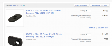
The reason I finally pulled the trigger is that 80/20.net is offering rare 15% off sitewide for a Black Friday deal that extends through Cyber Monday.
www.8020.net

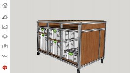
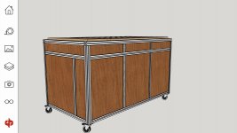
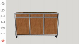
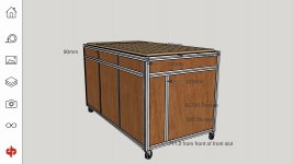
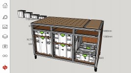
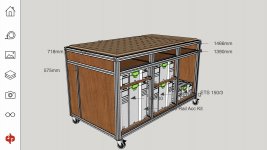
I ordered all the components I will need to build a 3' x 6' table with an MFT top with an extra 2' fold up wing on one end.  The table will serve as the outfeed table for my Unisaw with adjustable casters for leveling.  It will have easy reach storage for my Festool sanders, routers, clamps, accessories, Leigh jig and more.

I also ordered 80/20 parts for a router sled and rails that will attach to the table rails to give me 3' x 8' capacity for flattening slabs.

I'm super excited and will post updates when I start the build.
 
Sorry to dig into an old topic, but first thanks [member=8712]Richard/RMW[/member]  this has been an invaluable resource - over 66,000 reads!

I've likewise been working on plans for a (safer) more reliable router sled based on your tectonic wizardry [ seen here ]

This will be my 3rd and final* - no details on Sled#1 as it makes hairs on the back of my neck stand up. Sled #2 was based on Nick Offerman's version - while it felt much safer and provided a better finish, the limitations on wide pieces and ability to make consistent, uniform passes got me planning again.

I've been pricing profiles from 8020's Garage Sale and using https://openbuilds.com/ as a starting point for how I'd like this sled to function - conceptually a gantry system with adjustable widths and locking router plate. The idea is, rather than stretching across a width of the table back and forth (typically across grain), I'd include incremental-locking stops on the router plate with the primary motion being the length of the work piece, with the grain. Buildlog hopeful...

I've gathered the 15 series best suited for bench projects based on adaptability - the majority OpenBuilds Store platforms are based on the 20 mm profiles, I was shocked at how much more expensive the 15 mm profile is in comparison to the larger 20??? So this is the route I'll be taking for the sled application. 8020 Garage Sale is better than wholesale I suppose, but the shipping is still brutal. I'm now looking at Grainger who distributes 8020, shipped to store in 7 days for pickup, pay just TAX! Has anyone used Grainger as a supplier? I may be missing something but this seems like the most economical route, anyone?

[member=6237]deepcreek[/member] keep me in the loop on your build
 
Hntdpl, years ago when I first started using 8020, I contacted them via their website for a catalog.  They sent me one but also contacted their closest distributor, who then contacted me.  It may be that 8020 has a distributor close enough to you that will save you shipping.  Grainger sells practically everything under the sun, but they are expensive.
 
hntdpl said:
I've gathered the 15 series best suited for bench projects based on adaptability - the majority OpenBuilds Store platforms are based on the 20 mm profiles, I was shocked at how much more expensive the 15 mm profile is in comparison to the larger 20??? So this is the route I'll be taking for the sled application. 8020 Garage Sale is better than wholesale I suppose, but the shipping is still brutal. I'm now looking at Grainger who distributes 8020, shipped to store in 7 days for pickup, pay just TAX! Has anyone used Grainger as a supplier? I may be missing something but this seems like the most economical route, anyone?

Hey @htndpl - to clarify the 80/20 "15" series is 1.5"/38mm not 15mm, which probably accounts for the cost difference with openbuilds 20mm profiles.

I buy all my 80/20 from their eBay store

8' sticks of 1515 ULS are around $40 and when you combine stuff in your cart then ask them for a final price w/ shipping the shipping cost is less than what the eBay app calculates. To do this add everything to your cart then select "Request total from seller".

[attachimg=1]

They will send you an eBay invoice including shipping then you pay it if the total is acceptable to you.

Hope this helps.

RMW
 

Attachments

  • ScreenClip (Medium).png
    ScreenClip (Medium).png
    180.1 KB · Views: 5,783
hntdpl said:
I was shocked at how much more expensive the 15 mm profile is in comparison to the larger 20???

As Richard noted, the 15 series is imperial dimensioned and measures 1.50"

The metric equivalent is the 40 series and measures 1.57"

Be careful of Graingers, watch their prices. I was looking for a Milwaukee impact wrench and Graingers was $150 higher than anyone else.

 
Did a project that required many thousands of dollar worth of 80/20 stuff.
Thought it would be helpful to go through a distributor in case there were problems.
Turns out the distributors (Knotts in this case) don't actually stock the stuff.
They just pass the order on to 80/20.

When I needed more stuff I ordered through the 80/20 website, worked fine.
When I needed something really fast I ordered from McMaster.com

When the budget was exhausted and I needed something I checked out the 80/20 ebay store first.
 
Jesus, talk about an oversight  [unsure], I knew I was missing something...Thanks for the correction Richard and thanks [member=25351]rst[/member] for the tip, I'm going to look into local distribution. Back to the drawing board...
 
Hey Richard, thanks for sharing the awesome build!!  I’m building a cart also but have some variation to it and have questions on how to fasten the extrusion together.

I decided not to go with thicker top extrusion as I have supports underneath so there’s not much deflection with 4040 and I’ll notch out the inner t channel in a few spots so I can slip clamps inside when needed.

That said, how do you mount corners?  With end fasteners it seems drilling in both directions would blow out the center core of the extrusion and substantially weaken it. Does it weaken it even in regular butt joints?  It doesn’t seem possible to use this fastening method for butt joints which are opposite each other like the short vertical pieces on the upper level of my cart design. I’m thinking I’d need to use anchor fasteners for these instead?
 

Attachments

  • 065759BE-FAE4-4D7D-9961-A7F702D6EEF6.jpeg
    065759BE-FAE4-4D7D-9961-A7F702D6EEF6.jpeg
    161.2 KB · Views: 914
  • BB057607-75EB-4CFD-94A9-E12AE878F64F.jpeg
    BB057607-75EB-4CFD-94A9-E12AE878F64F.jpeg
    125.1 KB · Views: 764
  • 5B791583-5136-426D-894A-2F2F53B547D6.jpeg
    5B791583-5136-426D-894A-2F2F53B547D6.jpeg
    93.5 KB · Views: 776
  • CF17C5AD-B570-4F33-BB4D-36E9119D686E.jpeg
    CF17C5AD-B570-4F33-BB4D-36E9119D686E.jpeg
    125.2 KB · Views: 855
  • DE01D90F-55C9-48B6-9B2B-2A4F3965FA1D.jpeg
    DE01D90F-55C9-48B6-9B2B-2A4F3965FA1D.jpeg
    212.2 KB · Views: 975
  • D899731C-1EB5-4724-B08F-32F33BF9AC57.jpeg
    D899731C-1EB5-4724-B08F-32F33BF9AC57.jpeg
    175 KB · Views: 1,169
Hey Bugsy - couple thoughts:

As mentioned in PM, I used the end fastener method of all the connections except the top rails. This was to (1) keep cost down (the brackets are what kills you w/ 80/20) and (2) to get access to the end of the top extrusions for clamps. This method involves drilling an access hole in one extrusion (call it extrusion "A") and tapping the end hole of the corresponding one. In practice you need to have access to the opposite side of extrusion A so you can use a hex key to tighten the fastener. Because of this you can only use end fasteners on corner joints or T-joints. These images may help in understanding this - the arrows show where you need access to tighten the fastener:

[attachimg=1]

[attachimg=2]

In the second image you would not have access to be able to tighten the fastener for both the top and bottom extrusions.

My general thought on your design is that those small sections between the top and center rails are not necessary. Unless you are expecting to stand on top of your cart I doubt you would do anything to bend or flex the top rail in normal use.

I would also recommend you check the mounting holes on the drawer slides you plan to use. I had looked at having intermediate extrusions between each bank of drawers but the holes in the slides are not close enough to the end to mount into the t-slot. This is largely why I used plywood dividers between my drawer banks.

In case it helps anyone here there are 2 videos that depict what you have to do at home to use the end fasteners with 80/20. My power tapping video:


And 80/20's video on the fasteners themselves:


Hope this helps.

RMW
 

Attachments

  • InkedScreenClip_LI.jpg
    InkedScreenClip_LI.jpg
    823.4 KB · Views: 5,461
  • InkedScreenClip [1]_LI.jpg
    InkedScreenClip [1]_LI.jpg
    817.7 KB · Views: 5,397
Bugsysiegals said:
That said, how do you mount corners?  With end fasteners it seems drilling in both directions would blow out the center core of the extrusion and substantially weaken it. Does it weaken it even in regular butt joints?

Sorry - to respond to your question drilling access holes in 2 directions does not weaken the extrusion. On the corners however I used these 3-way corner brackets:

[attachimg=1]

RMW
 

Attachments

  • ScreenClip [2] (Medium).png
    ScreenClip [2] (Medium).png
    849.1 KB · Views: 5,795
Bugsysiegals said:
How did you mount the top to the cart?  I’ve found several brackets, etc., but am not certain what’s best or if there’s a cheaper alternative.

Top fastening kit

Panel mount bracket

Corner bracket

Panel Bracket

Richard made his own using a CNC machine.

I was going to ask a similar question, which is, what's a suitable alternative? I like how the top is recessed but slightly above the frame. I want to build a CNC machine, but my benches need to come first :)

I like the idea of the 80/20 Inc Aluminum 1.50" Roll-In Panel Mount Bracket 15 Series #2488 N (the 15 series version of the 40 series you posted). They don't require framing hardware, just a screw into the top. That screw should then hold the bracket in and load the weight on to the frame.

On a related note, has anyone tried Faztek? I'm in the process of finalizing an order with them for the first of four benches I want to build. They are about 25% cheaper than 80/20.
 
Great find on the drawer glides. The cheapo ones I used didn't have the holes close to both ends so weren't usable without the plywood panel. These glides also let you position the drawer at any height easily.

RMW 

Bugsysiegals said:
Thanks Richard. I may do some cabinet assembly and glue ups on top of the cabinet but the short extrusions are also so I can put drawers up top for rules, squares, sandpaper, clamps, etc. 

I’m considering 28” KV8450FM Soft Close Slides which I can get for somewhere between $10-15 per set which should mount similar to this cart, "MarxIng MFTM Multifunktionstisch Bausatz mit Anwendungsbeispielen" it's an MFT, as seen here ... Knape & Vogt - KV8450FM Installation
 
Bugsy as [member=67145]Dusty.House[/member] stated I made my own 1-piece top connectors shown midway thru this post.

An easier way would be to use a small piece of 5/16 AL or ply as a tab in the inside slot and then another small piece whatever thickness needed to raise your top to the height you want.  Drill a hole in both and screw up from below into the top.

RMW
 
Richard/RMW said:
Bugsy as [member=67145]Dusty.House[/member] stated I made my own 1-piece top connectors shown midway thru this post.

An easier way would be to use a small piece of 5/16 AL or ply as a tab in the inside slot and then another small piece whatever thickness needed to raise your top to the height you want.  Drill a hole in both and screw up from below into the top.

RMW

@RMW - What thickness did you end up with? Looking at your connectors it looks like they could easily be made from a block of HDPE with a rabbet to 5/16.
 
Dusty.House said:
Richard/RMW said:
Bugsy as [member=67145]Dusty.House[/member] stated I made my own 1-piece top connectors shown midway thru this post.

An easier way would be to use a small piece of 5/16 AL or ply as a tab in the inside slot and then another small piece whatever thickness needed to raise your top to the height you want.  Drill a hole in both and screw up from below into the top.

RMW

@RMW - What thickness did you end up with? Looking at your connectors it looks like they could easily be made from a block of HDPE with a rabbet to 5/16.

That's basically all they are. You will need to measure your extrusion and the top material to figure out what you need.

In my case  I wanted my top to be exactly 12.7mm (1/2") proud of the extrusion and I was using nominal 3/4" ply that measured 18mm. The 5/16" slot = 8mm.  The extrusion is 38.1mm & either side of the slot is 15mm (I dropped the .05mm) so my math worked out to be:

18mm - 12.7mm = 5.3mm
15MM - 5.3mm = 9.7mm
9.7mm + 8mm = 17.7mm

So I used full 3/4" (19.1mm) plastic and knocked 1.3mm off the top and then rabbeted 9.7mm to get the 8mm tongue.

Clear as mud...?

RMW 
 
Richard/RMW said:
Dusty.House said:
Richard/RMW said:
Bugsy as [member=67145]Dusty.House[/member] stated I made my own 1-piece top connectors shown midway thru this post.

An easier way would be to use a small piece of 5/16 AL or ply as a tab in the inside slot and then another small piece whatever thickness needed to raise your top to the height you want.  Drill a hole in both and screw up from below into the top.

RMW

@RMW - What thickness did you end up with? Looking at your connectors it looks like they could easily be made from a block of HDPE with a rabbet to 5/16.

That's basically all they are. You will need to measure your extrusion and the top material to figure out what you need.

In my case  I wanted my top to be exactly 12.7mm (1/2") proud of the extrusion and I was using nominal 3/4" ply that measured 18mm. The 5/16" slot = 8mm.  The extrusion is 38.1mm & either side of the slot is 15mm (I dropped the .05mm) so my math worked out to be:

18mm - 12.7mm = 5.3mm
15MM - 5.3mm = 9.7mm
9.7mm + 8mm = 17.7mm

So I used full 3/4" (19.1mm) plastic and knocked 1.3mm off the top and then rabbeted 9.7mm to get the 8mm tongue.

Clear as mud...?

RMW

Clear to me!

Thank you, this'll save me a ton of money in fasteners! Plus I think I can use the same principle on the sides to add strength to the peg board I plan to install. I have a bunch of 24" to use but my frame is 25". I can slot it into the top\bottom and use these to stabalise the sides.

Cheers

Ben
 
Richard/RMW said:
Seems like the past few weeks have been consumed by WORK and the boss insisting we have FUN on the weekends. We have a friendly disagreement as to whether playing in the shop qualifies as FUN, recently her position has prevailed. This weekend I put my foot down and refused to participate in FUN, so there was progress on the router table project which has been percolating for a while.

The table is 600MM square & designed to fit Woodpecker/Kreg inserts (am I the only person who didn't realize they were interchangeable until last week?):

Richard - How does the router table attach? Am I right in saying that you've used a joining strip that's permanently attached to the extension. You then slide t-nut in the other 1/2 of the extension plate into the main table from the left\right and tighten the bolt?
 
Dusty.House said:
Richard/RMW said:
Seems like the past few weeks have been consumed by WORK and the boss insisting we have FUN on the weekends. We have a friendly disagreement as to whether playing in the shop qualifies as FUN, recently her position has prevailed. This weekend I put my foot down and refused to participate in FUN, so there was progress on the router table project which has been percolating for a while.

The table is 600MM square & designed to fit Woodpecker/Kreg inserts (am I the only person who didn't realize they were interchangeable until last week?):

Richard - How does the router table attach? Am I right in saying that you've used a joining strip that's permanently attached to the extension. You then slide t-nut in the other 1/2 of the extension plate into the main table from the left\right and tighten the bolt?

Yes. In the 3rd photo in that post you can see (2) 1.5" by 3" 80/20 joining plates attached to the table. There is a second hole/fastener that fits into the slot on the top extrusion of the cart. The 90 degree legs rest against the intermediate extrusion.

RMW 
 
Back
Top