ryanjg117
Member
- Joined
- May 18, 2015
- Messages
- 328
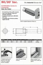
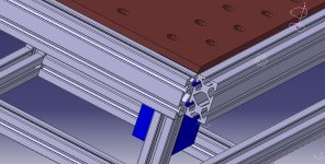
Yep, I contact 80/20 Technical Support today and they emailed me this page from the archives. They no longer offer this fastener (it didn't sell apparently) but it also says T-50 Torx. I'll have to check the tool chest to see if I've got it. [member=21642]Neohio[/member], since you were the first to successfully guess Torx, PM me your address and I'll ship you a temporary tattoo.