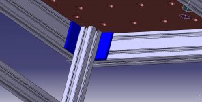
rst said:You can avoid the interference problem by attaching the leg on the inside of the angle bracket.
So something like this? What kind of fasteners do you use with this? Just screws and nutplates?
rst said:You can avoid the interference problem by attaching the leg on the inside of the angle bracket.
08G8V8 said:rst said:You can avoid the interference problem by attaching the leg on the inside of the angle bracket.
So something like this? What kind of fasteners do you use with this? Just screws and nutplates?
Richard/RMW said:08G8V8 said:rst said:You can avoid the interference problem by attaching the leg on the inside of the angle bracket.
So something like this? What kind of fasteners do you use with this? Just screws and nutplates?
In that configuration you can skip the blue angle and still use the access hole method, instead of the end fastener threading into the tapped hole you's use a t-nut in the 1530 slots.
RMW
And you may have to skip a bench dog hole in each corner. You’ll have 3” of metal to avoid.08G8V8 said:Richard/RMW said:08G8V8 said:rst said:You can avoid the interference problem by attaching the leg on the inside of the angle bracket.
So something like this? What kind of fasteners do you use with this? Just screws and nutplates?
In that configuration you can skip the blue angle and still use the access hole method, instead of the end fastener threading into the tapped hole you's use a t-nut in the 1530 slots.
RMW
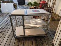
Yeah, I was trying to model a 3x3 angle to see what rst was talking about with nesting the leg inside the angle.
This would make things much easier and quicker to assemble, but would have to sacrifice 3” of storage in both length and width.
Sent from my iPhone using Tapatalk
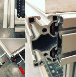
[/quote]Richard/RMW said:FWIW, if you decide to go with standard glides, after some trial/error I concluded that the best end panel is made up of 2 pieces of 1/2" laminated then you route a dado leaving an 8mm (5/16") tongue to slip into the slot. With the 15 series profile this leaves the inside face of the panel a couple MM proud of the extrusion and it's simple to mound the glides. These photos show what I am referring to.
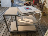
Michael Kellough said:Good solution, but you might want to move one pair of casters (or add another) beneath the inboard uprights. As it is, the bending resistance of the lower rails is keeping the top flat. When all the things are loaded on it might not remain flat.
Hi, what is the machine on the right side? It looks like some versatile multitool.neilc said:Richard
I like the design. Looks like it will give you a lot of storage plus some good strength. 80/20 is really great stuff. I drew my drawing in Sketchup like you and then sent it to the 80/20 rep for his refinements and quoting. Worked great to go back and forth that way.
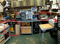
Here's an 80/20 bench I made for Systainers and other items. Might give you some ideas.
- The upper shelf uses 80/20 back rails with extra standoffs to extend around the overlay top. I like having the upper shelf so I don't have to bend down for every item. Most of the overhead Systainers actually go to a destination - like router bits to the CMS or the Vecturo being used away from the shop.
- The sortainers have a strip across the back to hold them in place and keep them from sliding. There is space behind them for seldom used tools.
- I did a vise on the end with the top offset to provide clearance and the wheels lock giving me a very sturdy bench
- Bottom shelf is for 'future purchases'
- I got the heavy maple top at Woodcraft. I have a couple of other tables drilled for 20mm holes and clamping
- The plywood shelves were finished with acrylic poly and dropped in place to fit between the posts during assembly. Looks like you are capturing yours in the 80/20 rails. I wanted mine to allow full access rather than having the rail extend above them, reducing access from the edge. They are all screwed down to T-nuts captured in the 80/20
- You can't see it but I captured a power strip on the side rails on the left side with T-Nuts for easy power.
[attachimg=#]
I debated doing pull out shelves but I have the full Systainer port to the left and several other pull out storage units in the shop.
Might give you some ideas.
Neil