Accuracy measured in microns?

smorgasbord

Member
Joined
Jan 7, 2022
Messages
1,059
While exploring commercial products for creating accurate angles (see this thread), I came across a large triangle from the well-known company BenchDogs.uk:https://benchdogs.co.uk/products/the-precision-triangle-bundle , which claims:

Accurate within 20 microns as recorded by our CMM machine, each Precision Triangle will be supplied with its own calibration report.

That's a pretty impressive statement. It's not clear what specifically they're referring to. I've seen resellers and YTers use that to say the laser markings are that accurate, but I suspect it's the geometry that is that accurate. Maybe both?

CMM (Co-ordinate Measuring Machines) can be pretty impressive, but are still subject to proper use. At any rate, I've not heard of generally available tools, not even Starretts or Zeiss or Mitutoyo, being made to that level of accuracy.

Anyone understand what is going on here? I'm not doubting the claim. I just don't understand everything that's being claimed nor how it's being measured and this is intellectually interesting to me. I do find it interesting that they'd feel the need to make that claim, given that the use of the tool is typically to measure of off MFTs, of which even the best are not near that accurate, not to mention that  the tracks on our tracksaws, tracksaw arbor runout, etc. are not measured in double-digit microns. But, I do appreciate that the more accurate one can affordably make tools, the better it is for results and at least repeatability.

 
Probably 5 to 7 years ago, a customer of mine was showing off his new QC measuring machine.  He was using it to get dimensions off of a machined casting.  The data for that casting was already in the machine.

He simply placed the casting on the work surface and pressed a “start” button.  The machine located all the edges, decided which surface was showing up, and decided on the orientation of that piece, and then made all the required measurements.  There were probably 30 salient dimensions to check.  The entire process took about one minute. 

Then they had to turn the casting on its side to repeat in the other dimension. 

I did not ask what the accuracy was.  I was amazed that the machine could identify the positioning of the measured part. 

It does not surprise me that they are working to really tight dimensions. 

My table saw came with a scale that reads in 16ths of an inch.  I consider that a reasonable measuring scale for wood working.  Microns are for other people, aliens and monsters.  [eek]

[The above does not actually represent the accuracy I have been known to work to.  I often make setup blocks for repeated cuts.  I am certain that they are accurate to within a few—maybe 0.003” to 0.005”—thousandths].  That is for repeatability.  I might not know the actual dimension.
 
Ya, accurate to within 20 microns...what does that mean? Flatness, straightness, thickness, perpendicularity, position of markings or maybe some other feature. That's a pretty empty statement all by itself. They don't even offer any further insight on their website, under the Information or Help & Support sections.  [mad]

So silly...
 
The significance is not being the weak link in your setup. Track straightness and arbor run out are most likely a lot larger. 
 
Maybe straightness of the edges? micron has nothing to do with a measurement of squareness.
 
Our QC Manager used to say that the most precise measuring device in the QC office was the granite flat plate.

I just googled the flatness tolerance for those flat plates and they come in three grades.

The highest grade is AA, and local flatness is 35 μin.  The article explains local vs overall flatness.

I do wonder how they are able to measure those deviations.
https://www.mitutoyo.com/webfoo/wp-content/uploads/15004A.pdf

 
I watched a video on precision a few weeks ago, I can dig it up if you really want, but at one point it talked about how to start from scratch, and the answer was to first get a flat surface. But, how to get it and know you've got it? The answer there was to grind three surfaces together and the only way that all three would fully contact one another everywhere along their surface was if they were all flat. Two surfaces and one could get concave while the other convex, but apparently there's a way of using a third to avoid getting there without knowing it.

As for the original micron accuracy, I do have to question how. The gantry-based CNCs and laser engravers they use are almost certainly high quality, but there's no way those linear rails and lead screws are anywhere near 20 microns accurate along their length.

That said, it does strike me that the gantry based machines have really revolutionized accuracy in affordable reference tools. I read a 40 year old article in Fine Woodworking that visited Starrett and the way they calibrated their try squares was with a granite surface and a known right angle (traceable to NIST?). They'd be in dark room with a back light and put the try square up against it and if it blocked the light it was good. If not it was either fixed or rejected. Today it seems the CMMs have taken over and any company in China even can have a really good CNC to make things that are more than accurate enough for woodworking.

I'm old enough to remember when we were warned that you couldn't put a try square inside another try square to check because a try square was only accurately square on the inside. Hence, the practice of NOT putting the inside handle against the edge while scribing along the outside of the blade. Bridge City Tool Works was one of the first to make squares that were square both inside and outside, but even those weren't calibrated inside to outside, just inside to inside and outside to outside.

Now squares have attached plates, sometimes even removable, and yet they insist they are still square (I got some Chinese ones supposedly meeting DIN /0 standards). Which means even the arms/plates have to be flat and with grooves parallel enough to the outsides, etc.

40 years ago, round bench dog holes were considered inferior to square because people were still using tail vises and expecting their workbenches to last multiple lifetimes. Today, almost everyone does round because of the tools created to take advantage of them, and they're comfortable replacing their MDF tops every few/several years as needed. Of course, no-one really had tracksaws back in the 1980's. Panel saws were the "best" way to break down sheet goods then, and they weren't cheap.
 
smorgasbord said:
I watched a video on precision a few weeks ago, I can dig it up if you really want, but at one point it talked about how to start from scratch, and the answer was to first get a flat surface. But, how to get it and know you've got it? The answer there was to grind three surfaces together and the only way that all three would fully contact one another everywhere along their surface was if they were all flat. Two surfaces and one could get concave while the other convex, but apparently there's a way of using a third to avoid getting there without knowing it.

If anyone wants to get into the weeds on precision, I'd recommend this fellow, he's a machinist with a Utube channel. He has a great video on using 3 each cast iron plates to lap a surface to AAA tolerances. He also has another video that will in real-time allow you to see how much a steel bar grows just from being held in the hand. That's the reason some micrometers have "insulation plates" attached to the mike.

He's also the reason I purchased a Kinetic Precision stone...I couldn't be happier.
=19
 
In the 20th century I worked for a large anatomic pathology practice.
I figured out that a million microns equals one meter.
When a specimen is to be examined microscopically it is embedded in wax and one micron thick slices are made.
Those slices are put on slides for the pathologist to study.
 
Crazyraceguy said:
Maybe straightness of the edges? micron has nothing to do with a measurement of squareness.
Actually. It is the way how this is defined and measured in metrology practice.

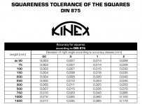
Example of German DIN standard for squares from Kinex:
(the standard itself is pretty expensive and not allowed for open publishing)
[attachimg=1]

Cheese said:
Ya, accurate to within 20 microns...what does that mean? Flatness, straightness, thickness, perpendicularity, position of markings or maybe some other feature. That's a pretty empty statement all by itself. They don't even offer any further insight on their website, under the Information or Help & Support sections.  [mad]

So silly...
Well, they make the (wrong) assumption that a general customer looking for precision would know on how a squares precision is defined.

Tricky! Given the US does not have a way to define it ..

I remember how a year or so ago I wanted to recomend some accuracy level for squares to a US-based member and found the hard way US does not have one. That still seems strange to me. Even Czechoslovakia, a country of 15 million, had/has one, Russians have one, Chinese have one, not to mention the German DIN stuff. I am pretty sure the Brisih have one too. But yeah. It is what it is.

BD folks being from Europe, where at least over here this is taught in the high school physics  classes *) (not specifically squares, but the basic concepts of metrology and standards) they would just assume their trades customers would know ... bad move.

[smile]

on topic:

...what does that mean? Flatness, straightness, thickness, perpendicularity, position of markings or maybe some other feature...
From your list these are covered "automatically": Flatness, straightness, perpendiularity,
thickness - no comment needed
position of markings - here the markings position accuracy is assumed as 1/2 the distance between the marks or better
EDIT: checked the web, here it goes "- Metric and Imperial Scale Markings, laser engraved accurately within 20 microns"

Strictly technically, specifying the squareness is enough. Is it enough to sell to the general customer ... probably not.

*) Actually, I distinctly remember us (Slovakia) being taught this in the 7th grade in a "technical works" class. Not much theory, but we were introduced into it for sure as I bought my first square then - we had none at home. Still have it. Not sure how it is now in elementary schools, but basics of metrology are covered in technical/trades high schools extensively. Same in Germany/UK and rest of Europe, from what I gather.

**) For markings positions, when done appropriately, the acccuracy is limited by their resolution possible, so the standards specify it like this and it is never specified on metrological kit - unless the markings are more accurate for some reason, then a specific markings precision can be specfied, usually it is printed along the markings on the tool

---
[member=49728]Ralph Mignano[/member]
Regardless what I wrote above, I believe Cheese does have a point. You sell to a LOT of non-professionals and/or self-made people. It is a good idea providing additional details on how the products are made wherever possible.

IMO it would be good to have a section of the description for the accuracy and precision aspects and "group" all the accuracy statements in it. Right now they seem to be spread all over.

Even if the info is technically redundant, it would still help folks who happen to not pay a company metrologist ...
[cool]
 

Attachments

  • Screenshot at 2024-05-14 11-00-03.png
    Screenshot at 2024-05-14 11-00-03.png
    58.4 KB · Views: 246
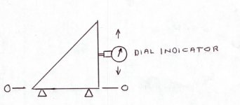
What they are saying is, with one edge defined as the datum, the other edge is within 20 microns (roughly one thousanth of an inch) of where it is supposed to be.

View attachment 1

If you want high accuracy squares, go to a metal-working site.  Even the cheapest squares will be far more accurate than typical woodworking squares.  But you will pay for it. 
Note that in this link, even the house brand squares are rather expensive, compared to woodworking aluminum squares.  If you see a Starrett or or name-brand square, the price can be down-right laughable.
 

Attachments

  • Square.jpg
    Square.jpg
    51 KB · Views: 32
Suburban Tooling's videos that talk about accuracy are worth a watch. Get a cylindrical square and an accurate surface plate and start from there.
http://www.youtube.com/results?search_query=suburban+tooling There are quite a few pertinent videos at the link. 

I have posted this beforehttps://brianholcombewoodworker.com/metrology-for-the-cabinetmaker-introduction/

Anyone who has seen his work will be inclined to think he knows what he is talking about. Unfortunately he has never done a follow up but I live in hope.
 
smorgasbord said:
I watched a video on precision a few weeks ago, I can dig it up if you really want, but at one point it talked about how to start from scratch, and the answer was to first get a flat surface. But, how to get it and know you've got it? The answer there was to grind three surfaces together and the only way that all three would fully contact one another everywhere along their surface was if they were all flat. Two surfaces and one could get concave while the other convex, but apparently there's a way of using a third to avoid getting there without knowing it.

A book which discusses this in detail is:
https://mitpress.mit.edu/9780262130806/foundations-of-mechanical-accuracy/
 
Steve1 said:
What they are saying is, with one edge defined as the datum, the other edge is within 20 microns (roughly one thousanth of an inch) of where it is supposed to be.

View attachment 1

If you want high accuracy squares, go to a metal-working site.  Even the cheapest squares will be far more accurate than typical woodworking squares.  But you will pay for it. 
Note that in this link, even the house brand squares are rather expensive, compared to woodworking aluminum squares.  If you see a Starrett or or name-brand square, the price can be down-right laughable.

Within 20 microns at what point? One inch from the corner is very good. At the end of the second arm is incredible.
 
Steve1 said:
What they are saying is, with one edge defined as the datum, the other edge is within 20 microns (roughly one thousanth of an inch) of where it is supposed to be.

View attachment 1

It definitely could be done that way, but you would have to disclose that distance as part of the spec, or it means nothing. 1 micron over 25mm is far different from 1 micron over 250mm
 
Note that the triangle comes with a "certification booklet" describing the test results. I haven't see what that looks like, though.
 
Crazyraceguy said:
Steve1 said:
What they are saying is, with one edge defined as the datum, the other edge is within 20 microns (roughly one thousanth of an inch) of where it is supposed to be.

View attachment 1

It definitely could be done that way, but you would have to disclose that distance as part of the spec, or it means nothing. 1 micron over 25mm is far different from 1 micron over 250mm
See the DIN standard table I posted. Length is the length of the arm, the values in the table are the allowed/maximum deviations along the end arm. The way this is checked is one compares the angle deviation against a better accuracy class reference square using straight edges. This mean not only that the deviation at the far end must be 20 microns or less, but also the straightness of the edges must fall within that as well.

With metrology of straight edges or squares, the stated values of allowed deviation are the maximums - i.e. the worst case scenario for a given square/tool.
 
Back
Top