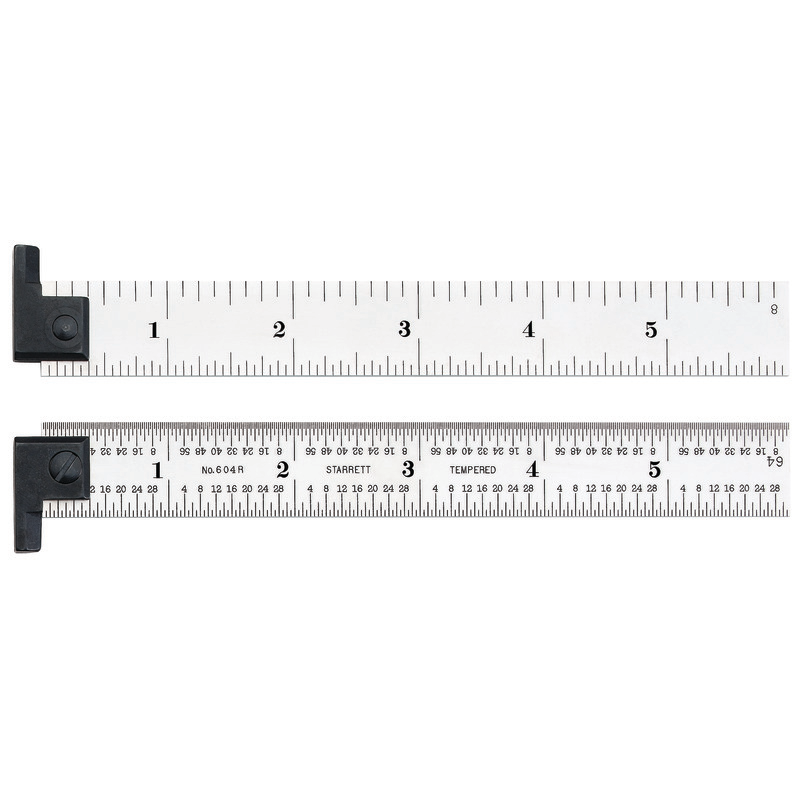
Take a close look at the
Starrett C635-E metal ruler:
It's marked from both ends. Note the tick marks for 20mm from the left and 130mm from the right. If what you claim is the correct way to read rulers, then the left edge of the 20mm tick would line up with the right edge of the 130mm mark (as viewed in this orientation). But, that's not the case - the 20mm and 130mm tick marks have their centers lined up, as do all the tick marks on opposite sides of the ruler.
Now take two metal rules and use one to measure the other's tick marks, but offset them by at least one tick mark. Line up the tick marks and see where the edge of the ruler intersects the tick mark on the other. It'll be at the center.
That the NIST engineer used the center of the lines, not the left edges, is also indicative that the correct way to read rulers is to use the center.
Try measuring your 4" block with a metal hook ruler as well.
Hate to merge in, but you are unintentionally conflating two things here.
When you
check/calibrate a tape measure for precision, you check for
TWO things:
A) Is the tape exact and uniform along its length - I am not sure of NIST procedure here, but both DIN(German) and ČSN (Czechoslovak) standards would require that calibrating a tape measure checks every 200 mm of its length for deviations. This is because you can have a tape that is exact end-end by accident but have big variations through the scale with "short" and "long" sections.
The standard calls for maximum accuracy here, so the most precise checking method is used - reference of a mark edge as is the rule in all metrology. If you ever did metrology, or even analytical chemistry, when you take visual readings of a scale, and you are after maximum precision, you never go to the centers of the mark. The way a human eye works is it is reference-based.
Meaning you will be more accurate if you take two "left" readings or two "right" readings of a scale and subtract.
When proper science classes are*) done, this is hammered into kids as the first thing as it is useful in daily life. Pretty sure it was at our 6th year labs (K7 US terms).
B) Is the end stop zeroed? To do this, you check the end position vis-a-vis a given mark close to it, say at 200 mm. You do it using magnification kit ideally.
When you did both these readings, you
then combine them into a single calibration value.
----
In short, there are two rules to read a scale for best precision:
1) Whenever possible, calibrate (and read)
either the left
or right sides of the marks. Do not read by the center, excepting point 2).
2) Always
keep note of how a given instrument was calibrated if you you cannot follow rule 1).
Scales starting at zero
cannot use the left/right approach
thus are calibrated to the center of the mark. While this
is the less accurate method, a scale starting at zero cannot be made other way.*)
---
What this all means for practice:
1) When you can, always take a relative (subtractive) reading using the left
or right edges of the marks on both ends of your measurement.
/With tape measures this is even more important as the end stops are the things the most abused/damaged. A tape measure will usually keep its relative accuracy even after its end stop gets bent inevitably./
2) Be aware that the ends of zero-starting
measuring instruments are calibrated to the center of the mark, so when using the zero start/stop, you must use that.
3) When calibrating scales
on machines, for maximum precision calibrate to the left
or right edges of the marks
and make sure every user of the equipment is aware which side it is calibrated to on that specific machine.
If you cannot ensure all users are aware which side a scale a machine was/is calibrated to, a common scenario,
then it is preferable to eat the precision loss and calibrate to the center than having people using the "wrong" side. In machine shops it was common to have shop-wide policies of "left of mark" or "right-of-mark" readings when manually controlled machines were in use by multiple people. In such settings, many workers had no clue why and just followed the policy, so lots of anecdotal "this is the correct way" stuff is out there. These days of CNCs, it is mostly irrelevant as anything needing to be precise is not made by hand/eye.
---
Now to put this all in context.
We are talking about precision differences in the 0.1 mm (0.005") range and smaller. Talking about this stuff
in the context of studs positioning would be just ridiculous. But above is how it goes if you
need the best precision from a given scale reading.
If you do not
need it, or multiple users are involved, just stick to using mark centers which are unambiguous. No point wasting time/energy on precision that is not required.
----
*) were done, notice the "proper" term too. To align us to US/Western "quality education", Physics labs at middle school level were abolished 20 yrs ago and the Chemistry labs were castrated to a teacher show by EU about 10 yrs ago to "protect the kids from chemicals knowledge". These days one will probably hit this only at a trades school or a natural sciences higher edu course. It still is the fundament of visual instrument reading, nonetheless.