[member=64013]ElectricFeet[/member] Thank you so much for the detailed designs and solutions. It’s going to save me a lot of trial and error. I’ll take a go at options two and three for a sled and mitre solution.
I have an Incra 1000HD that I’d like to use, so I spoke with Incra to get their input on replacing the rail, and they’ve provided some very detailed instructions. I’ll include them here in case it’s useful to others.
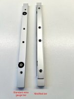
Yes, transplanting the protractor mechanics to a different bar is a straightforward job in your own shop. A wooden or plastic runner won't give you the consistency you want…the bare minimum would be a stiff composite like phenolic, but a steel or aluminum miter bar is best.
You can either use the guide bar from the saw's original miter gauge as a destination, or sometimes spare bars are available from the saw's manufacturer. Because Incra miter gauges are calibrated for “squareness” after they're assembled, there's some forgiveness in the locations of the 4 threaded holes…+/- 1/64" (0.4mm) is close enough.
Also, if the original miter bar is loose in the slot, this doesn't affect accuracy with proper technique…I can expand on that if you like.
______________________
If you want to transplant the Incra mechanics onto a different bar, this method doesn't require special tools beyond the standard thread taps found in hardware stores –
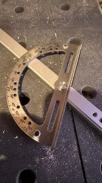
1 - Remove the adjusting discs, protractor, & lever assemblies from the Incra miter bar. Take a photo or otherwise note the location of the various spacers and washers around the angle lever before disassembling. The pivot bolts for the lever and protractor are usually very tight.
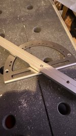
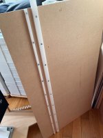
2- Clamp the bar on top of the saw’s original miter bar so the long edges are parallel. The bars don’t need to be centered on one another, just align them flush along one edge and clamp them down on your workbench.
3 - Select drill bits that are sized to fit through the threaded holes in the Incra miter bar without a sloppy fit, and then use a hand-held drill to gently mark the hole locations in the destination bar using the Incra bar as a template. You can wrap masking tape around an undersized drill bit to snug up the fit in the Incra miter bar’s threaded holes and help keep the bit centered.
4 - Mark the hole locations, but don’t drill large dimples that will cause the bit to wander during the final drilling. Unclamp and separate the bars after you've marked the holes.
5 - Set up a fence or clamp a board across your drill press table to provide a reference for the edge of the miter bar as you drill it. This guarantees that the series of holes will be in a straight line and parallel to the edge of the bar. The holes don't need to be centered on the miter bar.
6 - The thread sizes used are 1/4”-20 at the knobs and #10-24 at the pivot bolts, so the holes should be sized appropriately to accept those thread taps. There is some leeway, but the ideal sizes are a #25 drill bit (0.1495”) and a #7 drill bit (0.201”). Bits sized to the nearest 1/64" should also work fine.
Make sure the drill bits are SHARP… Traditional hardware stores sell bits individually, and it's worth buying a couple fresh ones if there's any question.
7 - When threading the holes, a few drops of thread cutting oil is perfect (sold in the plumbing aisle), but heavier machine oil can work. There's a ton of info on the Internet & YouTube about tapping threads into mild steel like our miter bars if you need a refresher on the process.
8 - With the holes drilled and threads tapped, transfer the parts to the new bar. The pivot bolts should be fully tightened, and they bottom out against the top of the miter bar. It's normal for the nylon spacers under the head to be loose after the bolts are tightened.
9 - With the pivot bolts fully tightened and the locking knobs in place, loosen the fence mounting bracket and calibrate the gauge to cut square when the gauge is locked at zero degrees.
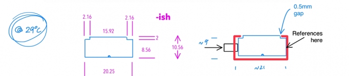
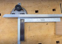
The miter gauge owner's manual will illustrate squaring against the saw blade as a starting point, but calibrating against the saw’s miter slot is better because there are fewer variables like saw alignment & blade flatness…this is the most accurate no-test-cut method.
This photo illustrates the process –
link to diagram