Bugsysiegals
Member
- Joined
- Mar 19, 2016
- Messages
- 893
I like processes which are super easy to remember as I can be forgetful. I also desire things to be accurate, repeatable, and with the least chance for me to make a mistake as I tend to do even with metric (off by 5 or 10 even when I'm reading the rule right side up!!!). I'd like to understand if anybody has been able to come up with a way to use the LR32 which meets these conditions.
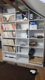
More specifically, I'm trying to drill holes for 3 drawer slides and I'm struggling to find a process which meets my idea of KISS. If I lay the guide rail vertically, which I suspect is the correct orientation regardless of shelf pin vs drawer slide holes, I can setup the offset for the first/last hole, but cannot reach the middle holes without measuring, marking, moving the rail, aligning the bit to the mark, etc., etc. While this works, IMO, its not KISS.
My cousin suggested drilling just the first/last holes, mounting the drawer slide, and drilling the rest by hand, but that defeats the purpose of such an expensive tool and is tedious.
I'd considered to use the rail horizontally for drawer slides but even in this way I'd need custom endstops, no problem with 3D printer, but would still have to measure, mark, etc., etc. which is also not KISS.
I've the Seneca parallel guides which made me consider these might work but there's many issues with these such as setting the endstop manually several times (user error). Add/subtract "x" from the rule, even if you align it for this process, since it will not be the same when flipping the panel 180 degrees (user error). Again, not KISS.
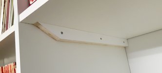
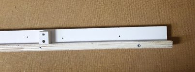
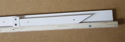
That said, the best I can think of would be to have longer alignment bars (T-Track, 8020, etc.), which are adjustable like the existing alignment bars, and would have holes spaced 32mm apart. In this way, you insert a locating pin in the first hole, push the guide rail back so the pin is touching the front edge, align the bar for 37mm offset, drill the first hole, move the locating pin back 3 holes, and are ready to drill another hole 96mm back from the first hole. I could easily design a 3D printed mount if it's different than the original bar stock but am not sure how I'd get it drilled out with consistent 32mm spacing. I could use the LR32 to drill these holes in 2-3' pieces of wood and make a mount but this is rather cheap and also prone to expand/shrink. I seen Woodpeckers and Veritas have some 32mm drilled aluminum stock for shelf pins but perhaps you've some other ideas...
So ... has anybody done anything like this or have another solution which is really KISS?
More specifically, I'm trying to drill holes for 3 drawer slides and I'm struggling to find a process which meets my idea of KISS. If I lay the guide rail vertically, which I suspect is the correct orientation regardless of shelf pin vs drawer slide holes, I can setup the offset for the first/last hole, but cannot reach the middle holes without measuring, marking, moving the rail, aligning the bit to the mark, etc., etc. While this works, IMO, its not KISS.
My cousin suggested drilling just the first/last holes, mounting the drawer slide, and drilling the rest by hand, but that defeats the purpose of such an expensive tool and is tedious.
I'd considered to use the rail horizontally for drawer slides but even in this way I'd need custom endstops, no problem with 3D printer, but would still have to measure, mark, etc., etc. which is also not KISS.
I've the Seneca parallel guides which made me consider these might work but there's many issues with these such as setting the endstop manually several times (user error). Add/subtract "x" from the rule, even if you align it for this process, since it will not be the same when flipping the panel 180 degrees (user error). Again, not KISS.
That said, the best I can think of would be to have longer alignment bars (T-Track, 8020, etc.), which are adjustable like the existing alignment bars, and would have holes spaced 32mm apart. In this way, you insert a locating pin in the first hole, push the guide rail back so the pin is touching the front edge, align the bar for 37mm offset, drill the first hole, move the locating pin back 3 holes, and are ready to drill another hole 96mm back from the first hole. I could easily design a 3D printed mount if it's different than the original bar stock but am not sure how I'd get it drilled out with consistent 32mm spacing. I could use the LR32 to drill these holes in 2-3' pieces of wood and make a mount but this is rather cheap and also prone to expand/shrink. I seen Woodpeckers and Veritas have some 32mm drilled aluminum stock for shelf pins but perhaps you've some other ideas...
So ... has anybody done anything like this or have another solution which is really KISS?