Entry hall table for a niece

derekcohen

Member
Joined
Jun 22, 2008
Messages
933
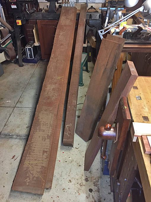
I thought that the build might begin with preparing the panels, since there has been some interest in the past shown in the shorter Hammer K3 sliders. Mine has a 49" long slider and a 31" wide table for the rip fence.

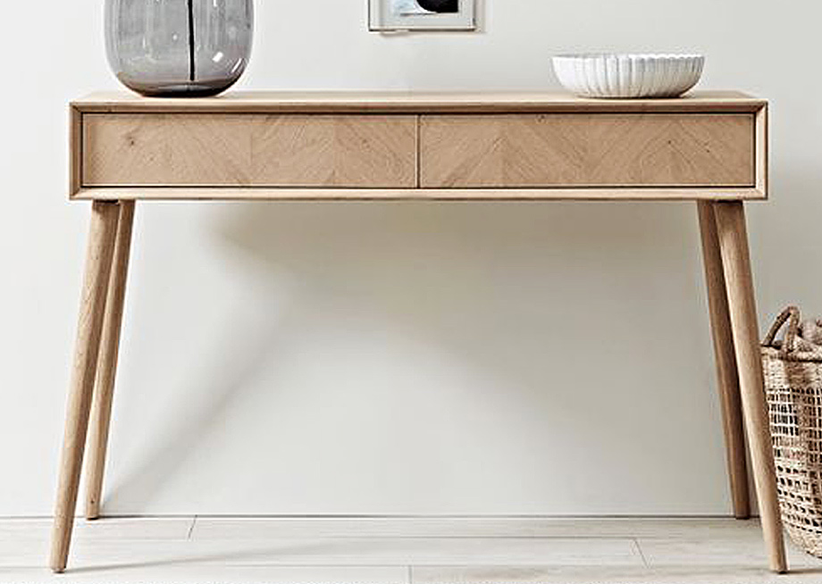
The build is an entry hall table for a wedding present for a niece. Her choice was this mid century modern piece, which will be the basis for the build. My job is to re-invent it somewhat.

Jes-Entry-Table.jpg


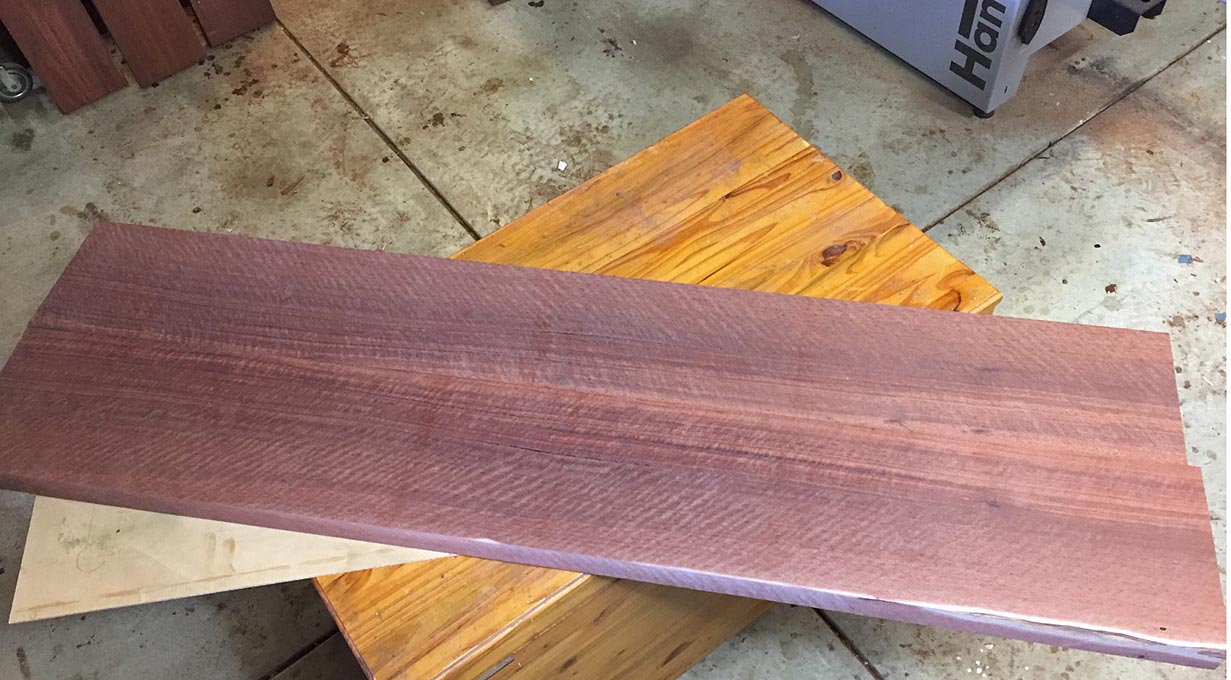
She wants Jarrah, and I have managed to find something spectacular ... a subtle fiddleback (curly) set of boards that will make a book match (as they are only about 9" wide each).

Wood1.jpg


Resaw7.jpg


Resaw9.jpg


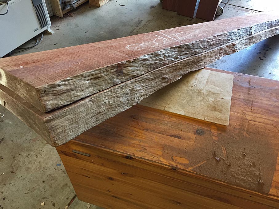
Most imagine that the value of a slider lies with cross-cutting. It certainly is so. However it is the rip using the slider - rather than the rip fence - which is so amazing.

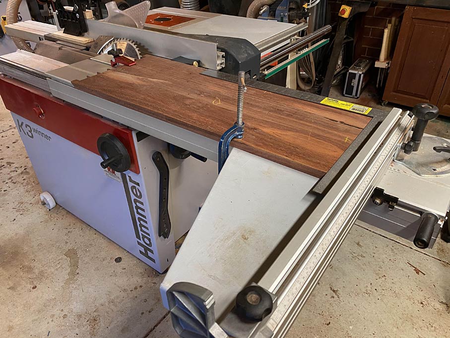
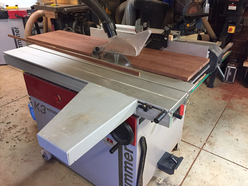
One side of each board was to be ripped on the slider, before being jointed and resawn. Ripping on the slider is such an advantage with life edges. No jigs required. No rip fence to slide against. Just clamp the board on the slider, and run it past the saw blade. The long sliders can complete the rip in one quick pass. It occurred to me that I should take a few photos of ripping to width since the boards are longer than the slider.

Here you can see that it comes up short ...

Resaw10.jpg


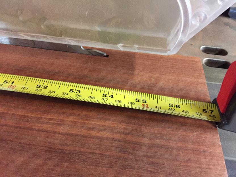
In actuality, with the blade raised fully, there is a cut of nearly 54" ...

Resaw11.jpg


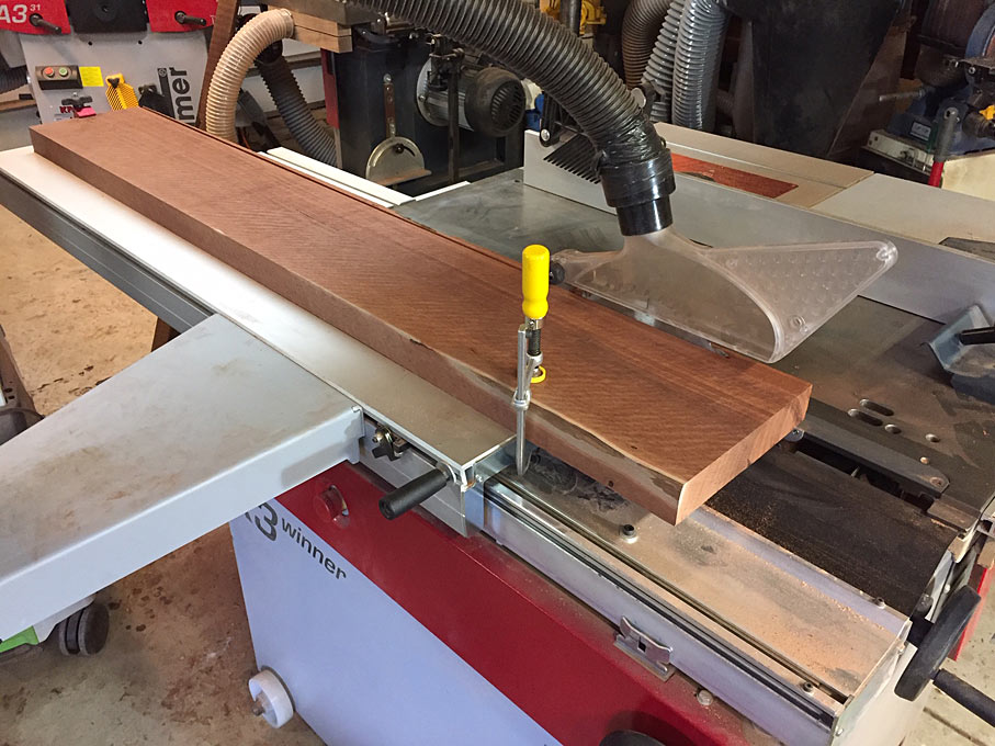
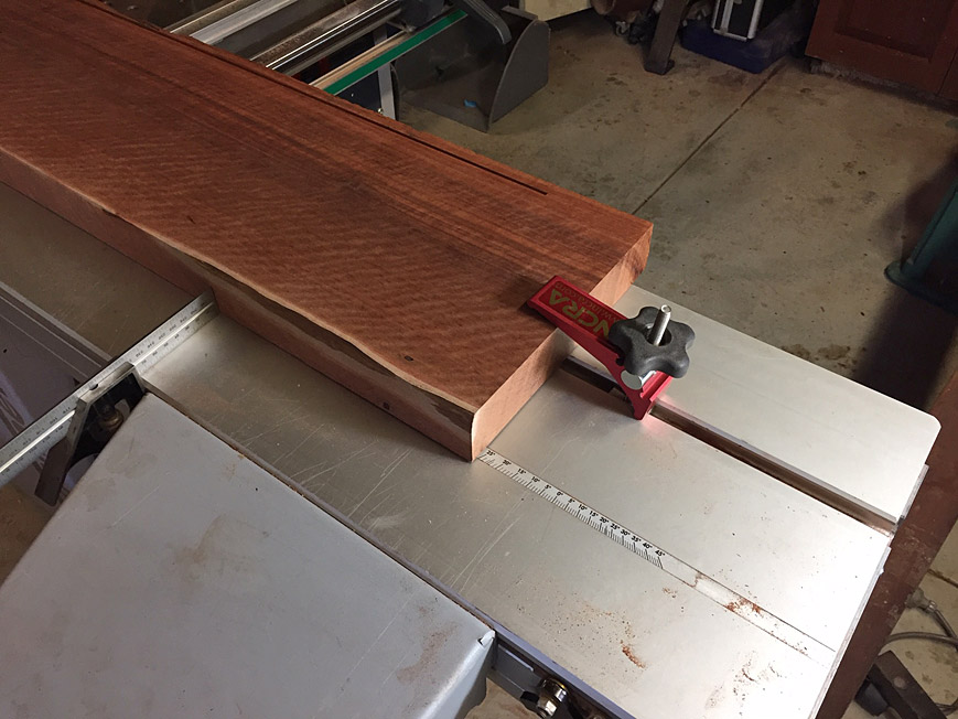
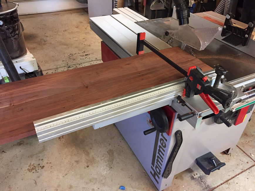
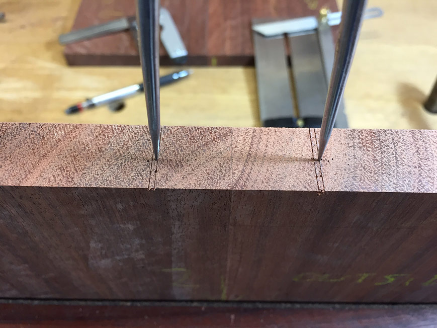
The solution is to use a combination square to register the position of the side of the board at the front, and then slide the board forward and reposition it ...

Resaw12.jpg


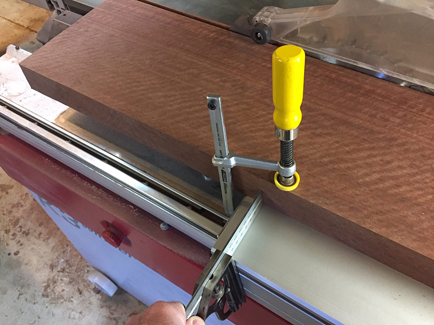
... and repeat at the rear ...

Resaw13.jpg


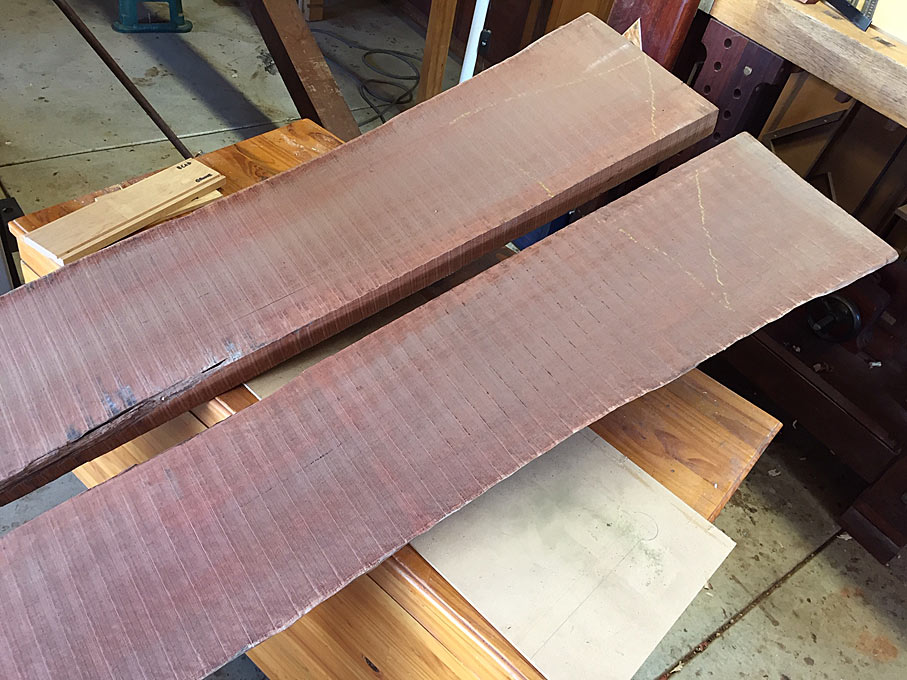
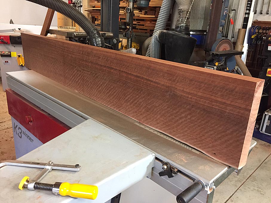
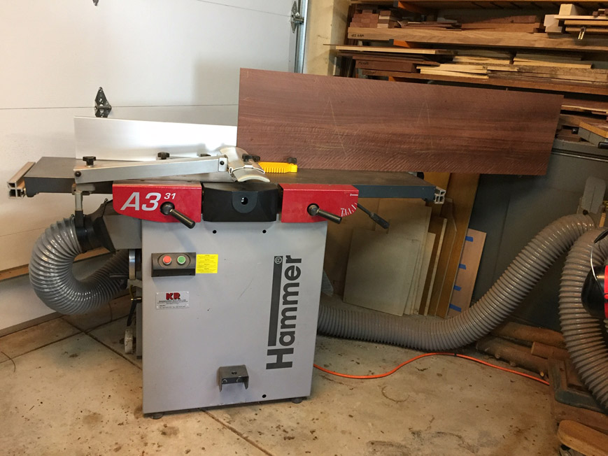
The result is a pretty good edge, one that is cleaned up on the jointer in 1 or 2 passes, and then ready for resawing ...

Resaw14.jpg


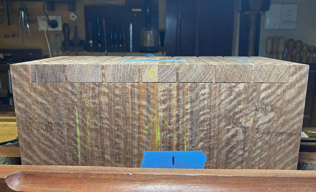
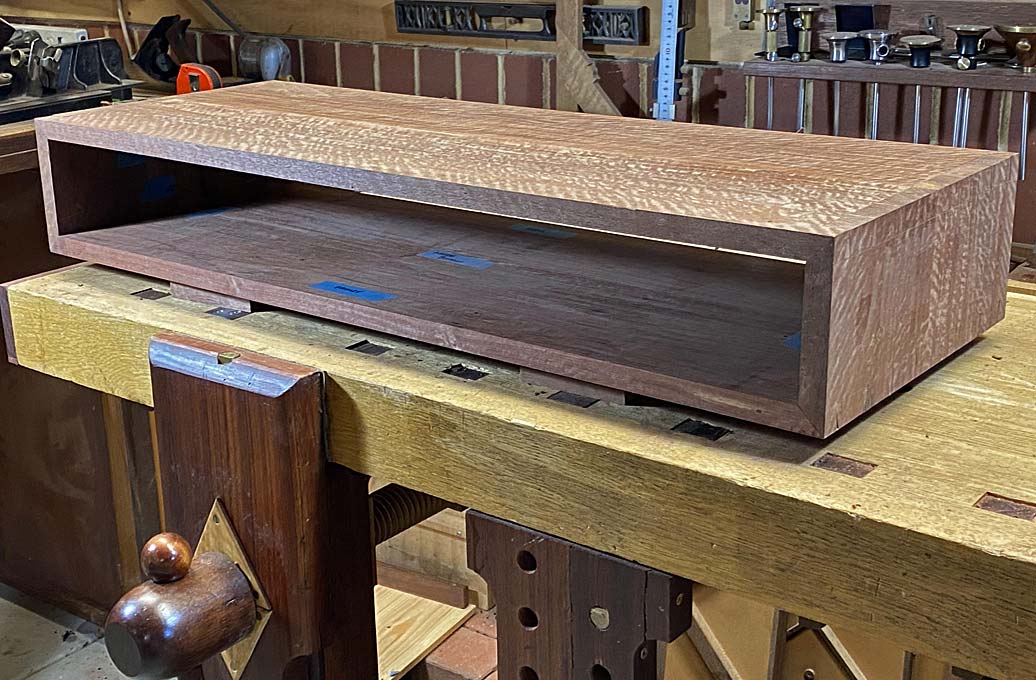
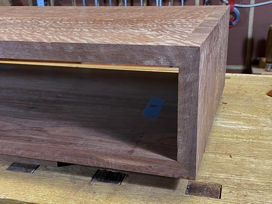
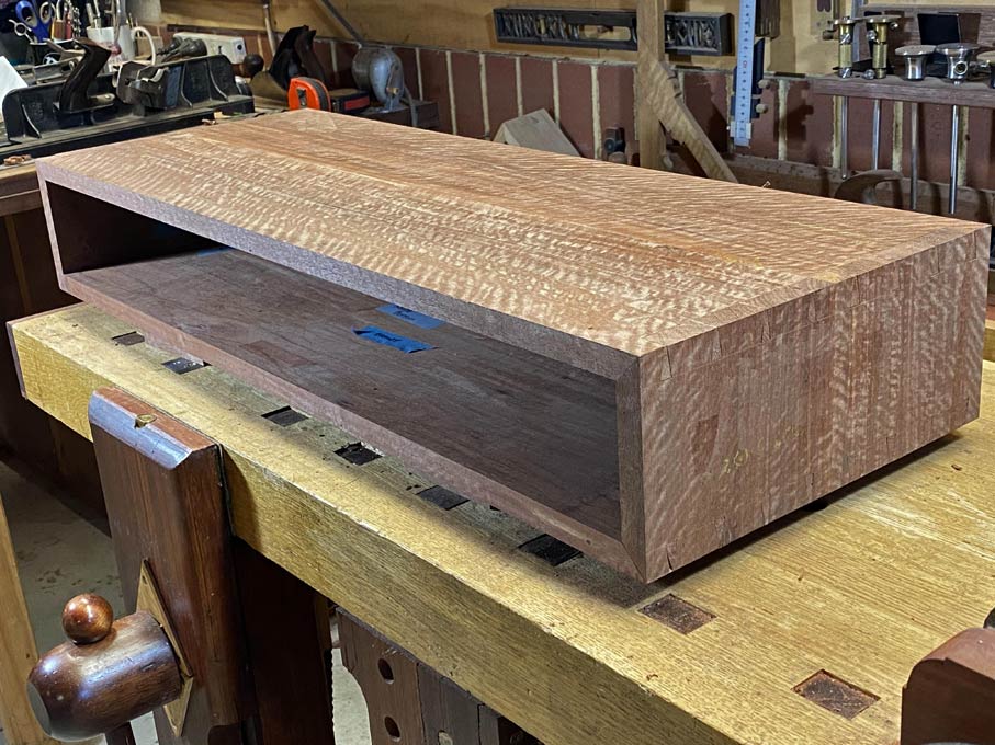
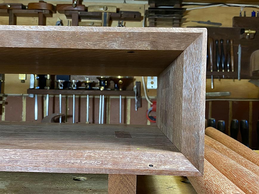
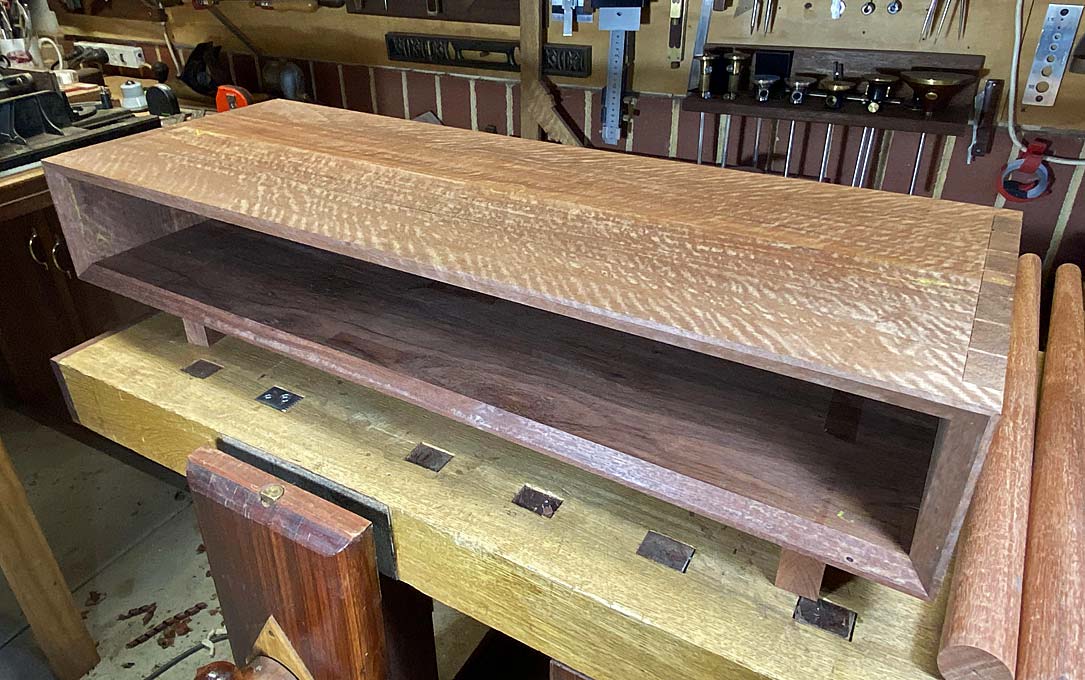
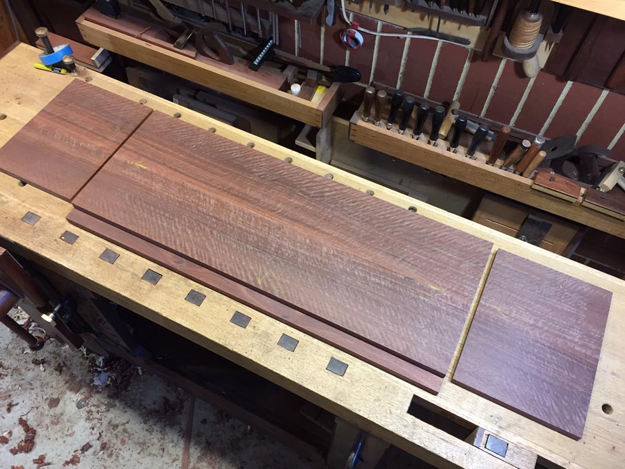
This is the glued panel. It is long enough to make a waterfall two sides and top section (still oversize) ...

Resaw15.jpg


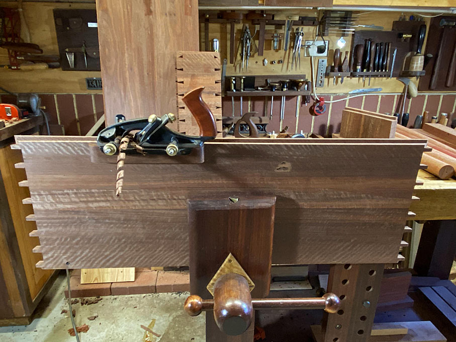
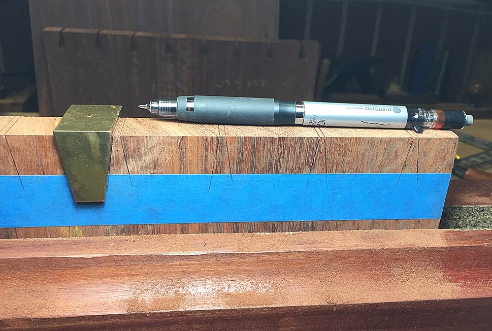
The following photo shows the lower section at the rear. What I wanted to show is the way boards are stored. Since I shall not get back to this build until next weekend, all boards are stickered and clamped using steel square sections.

Resaw16.jpg


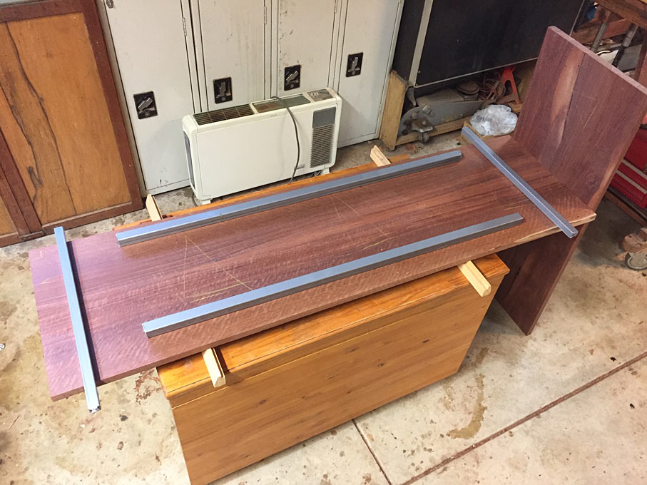
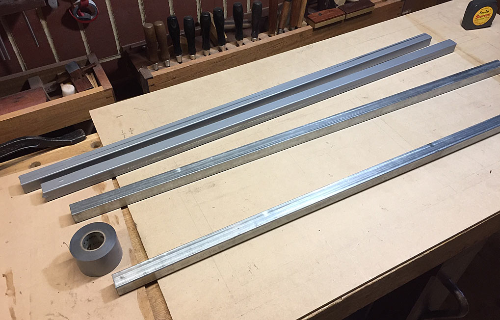
The steel sections are inexpensive galvanised mild steel. These are covered in vinyl duct tape to prevent any marks on the wood and ease in removing glue ...

Resaw17.jpg


Done for the day ...

Resaw18.jpg


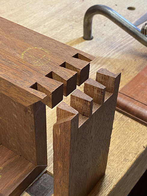
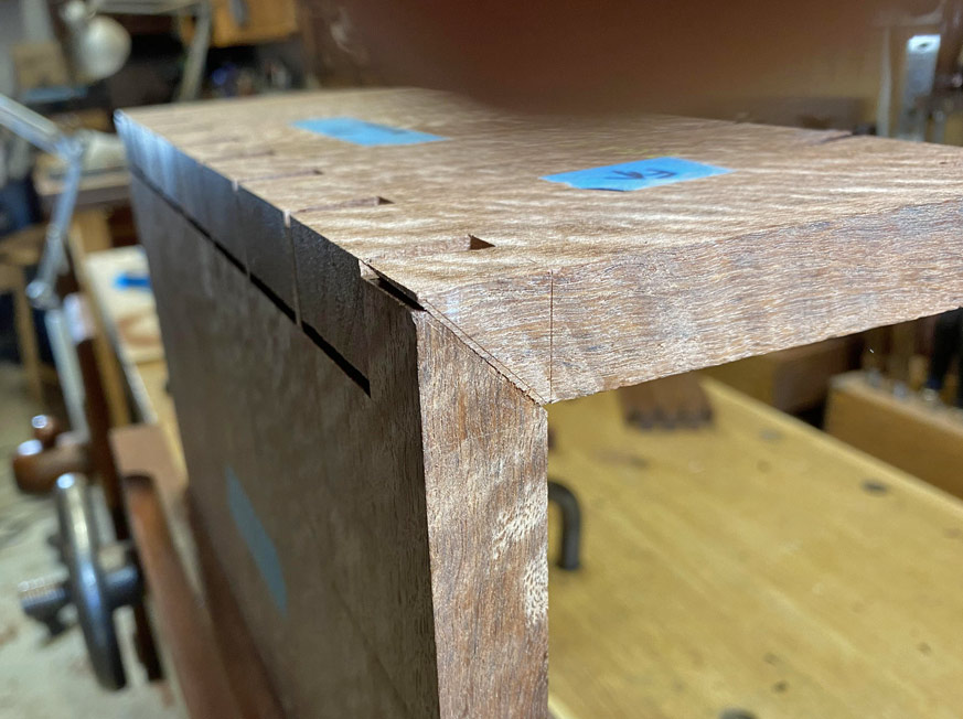
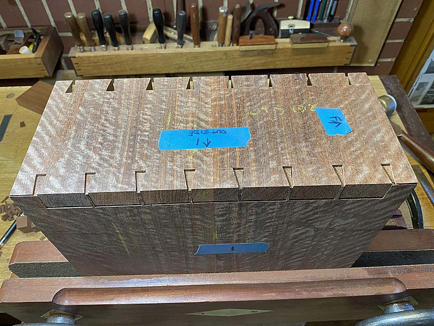
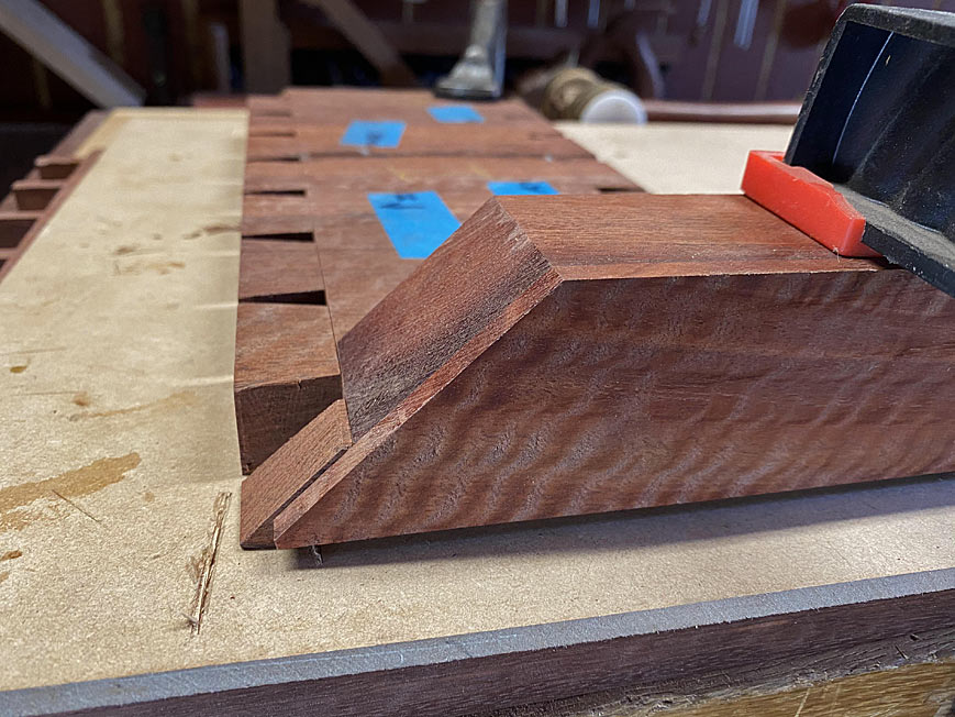
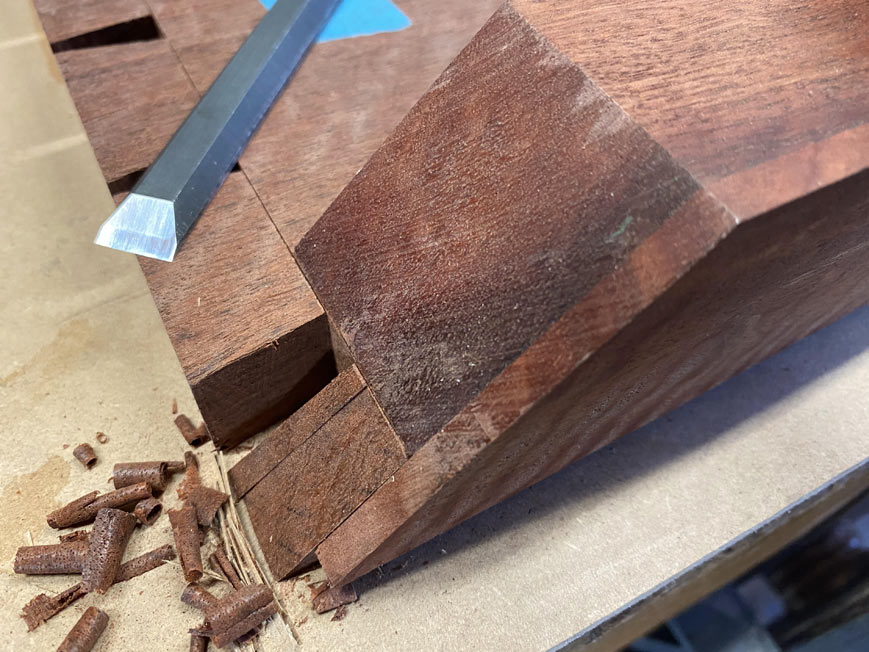
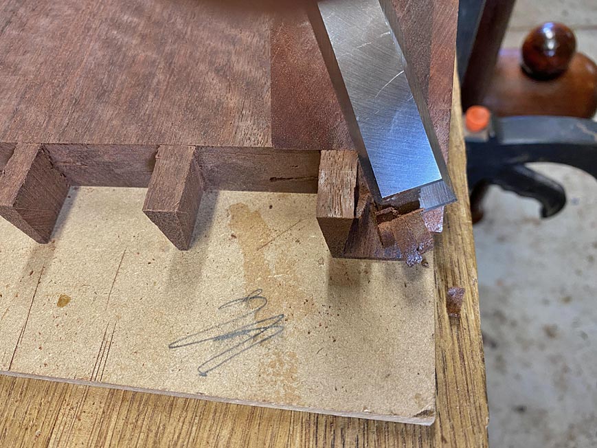
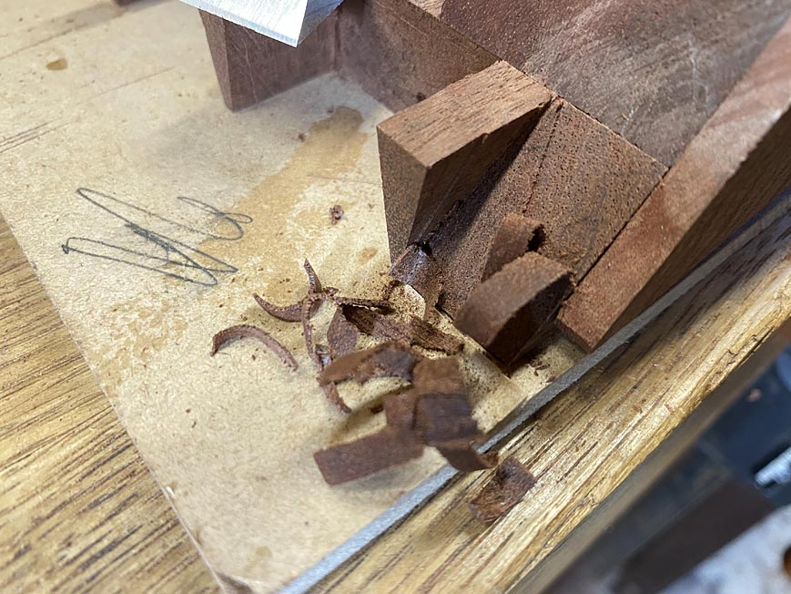
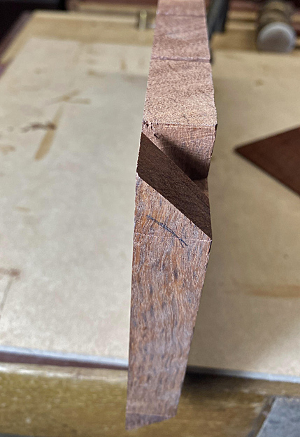
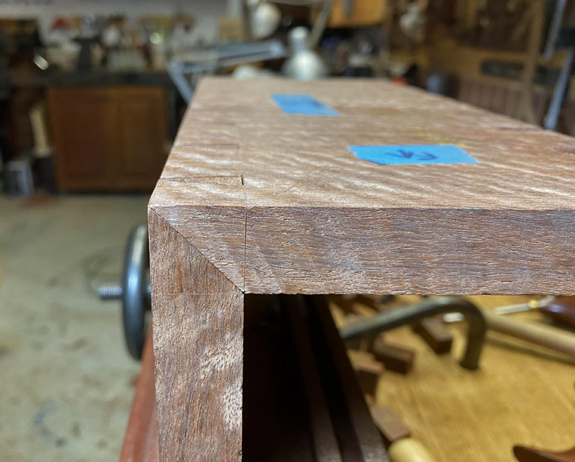
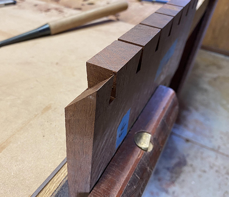
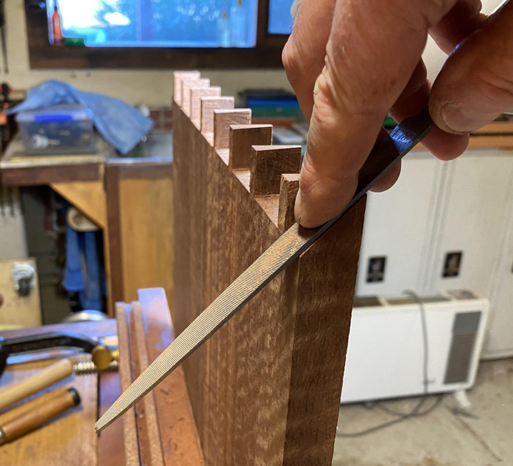
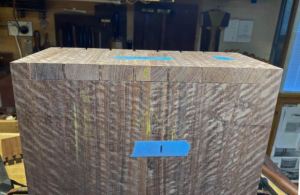
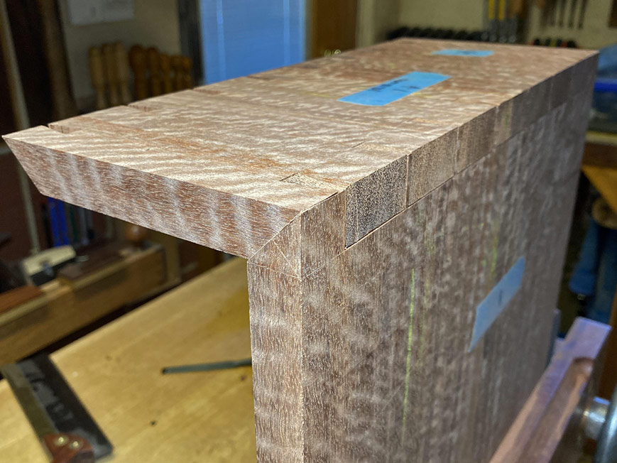
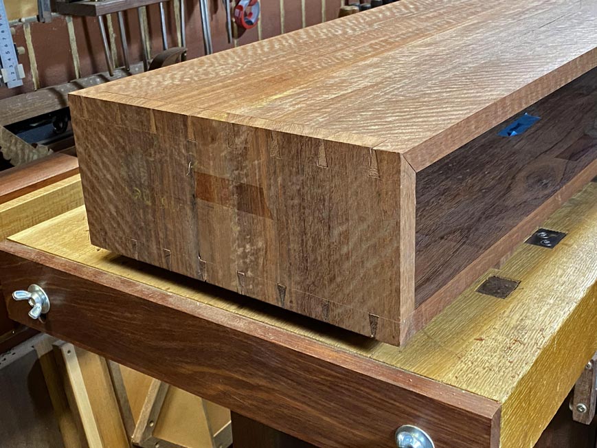
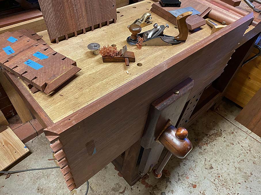
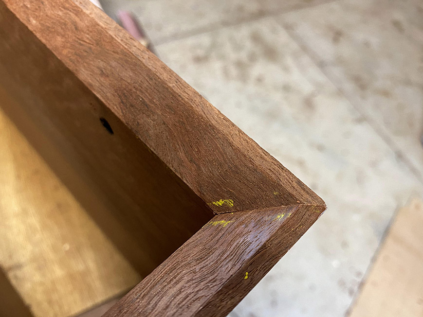
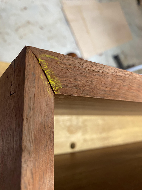
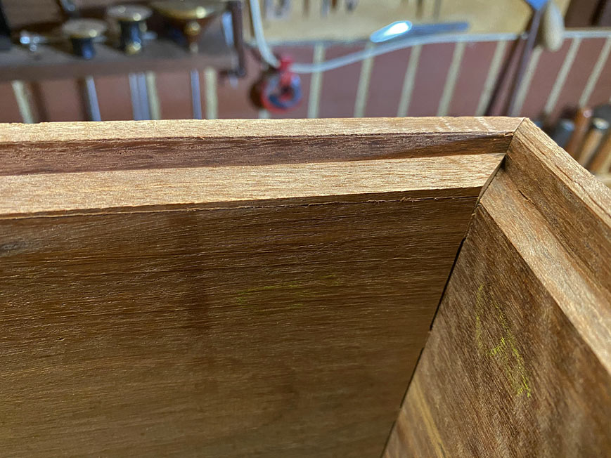
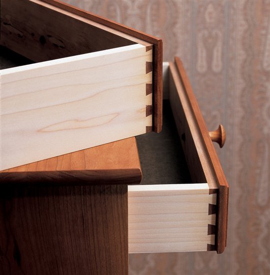
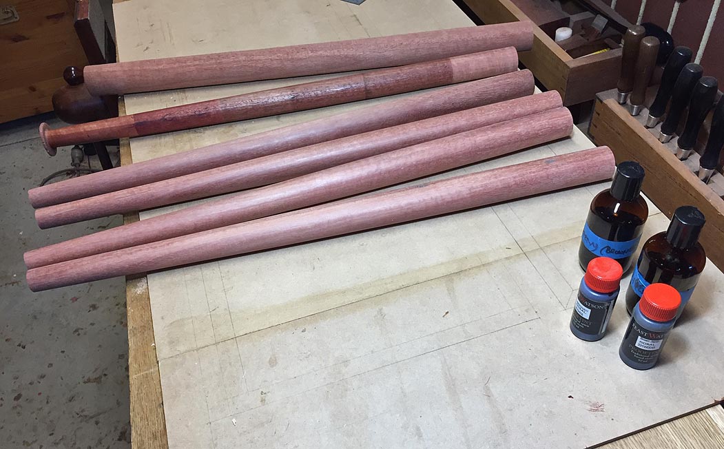
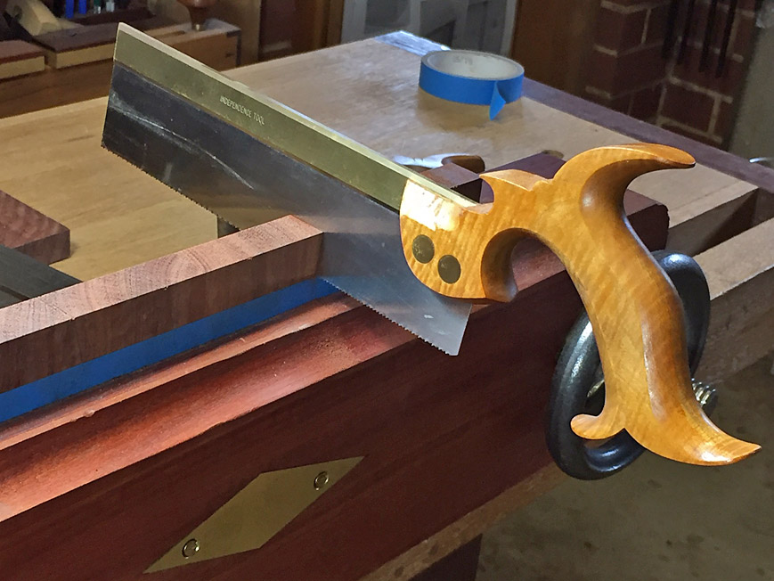
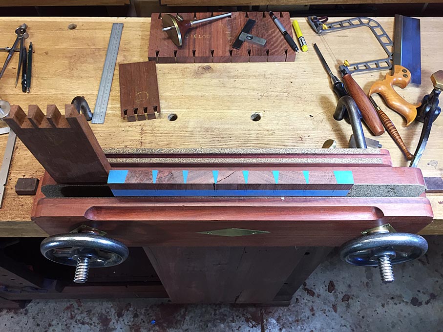
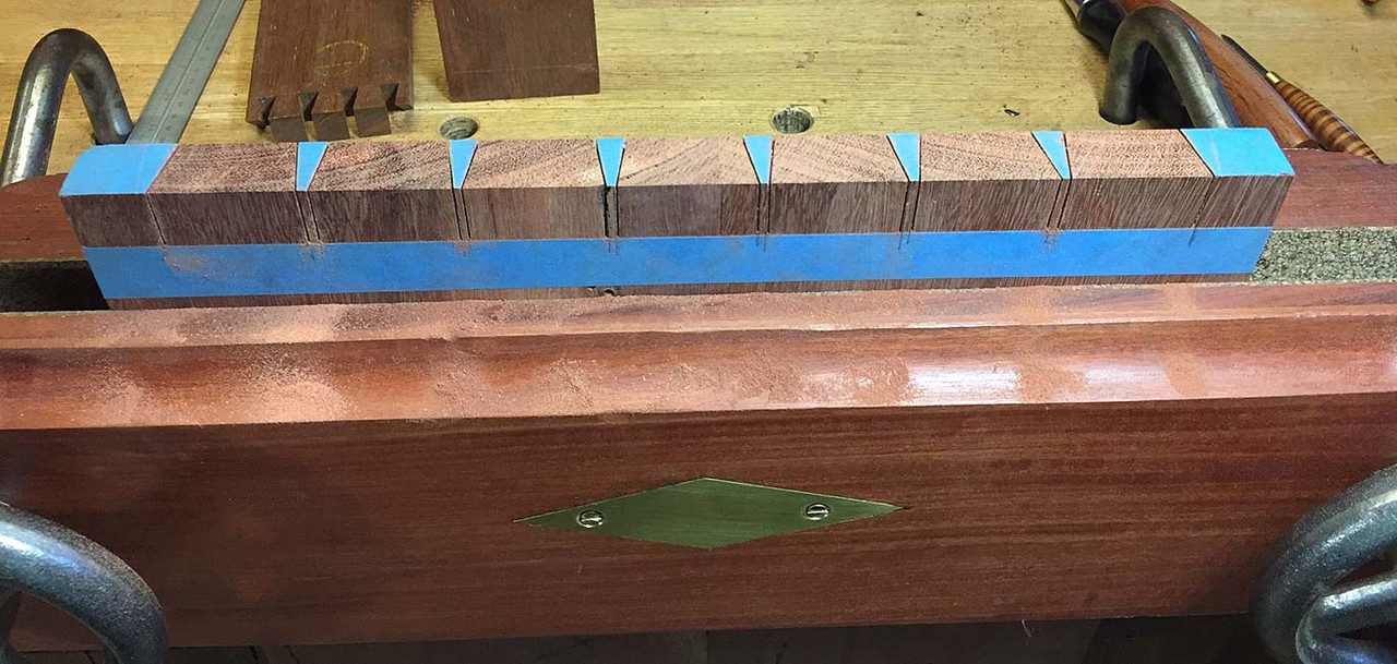
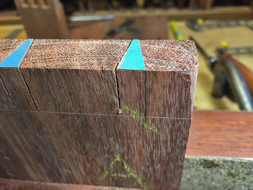
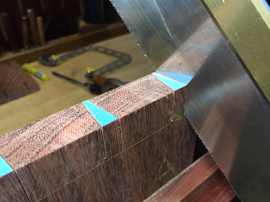
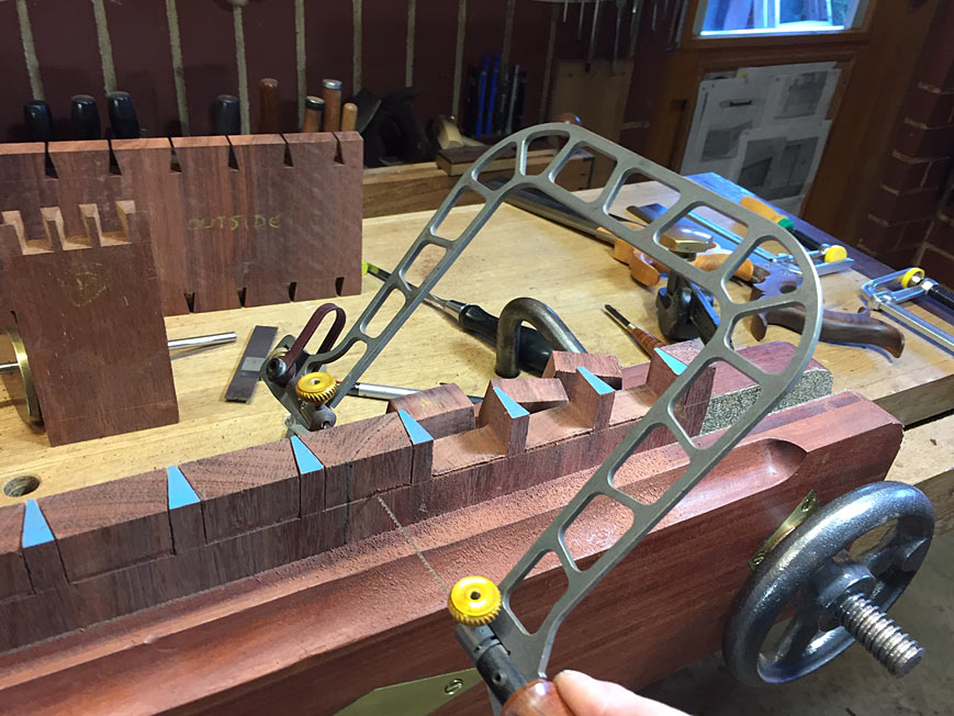
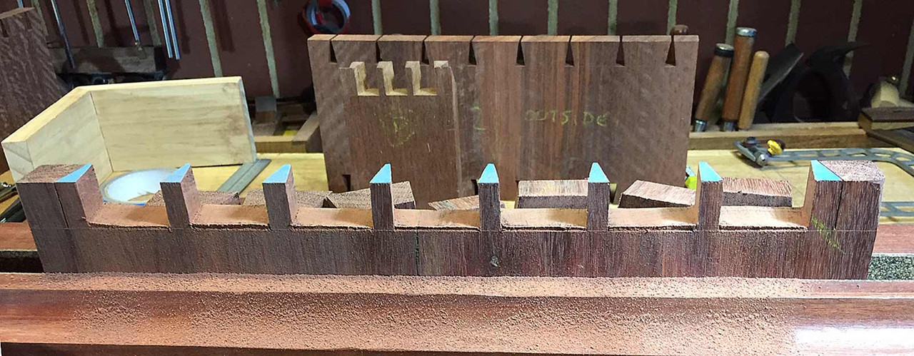
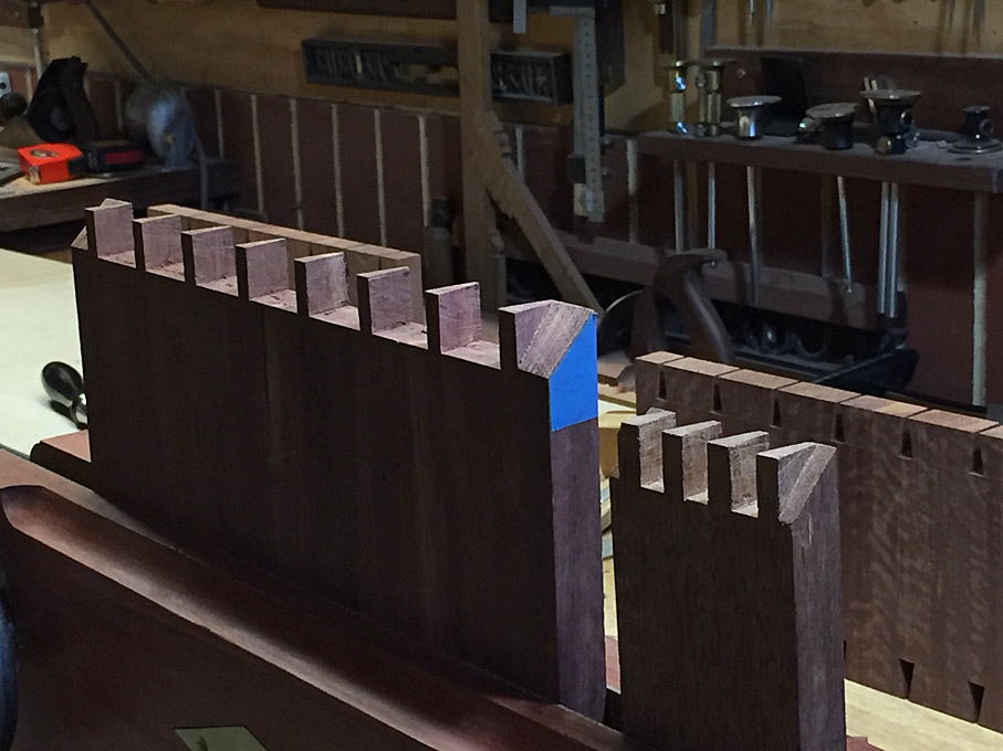
Enough for the case (top/bottom and sides), which will be through dovetailed with mitred corners, the stock for 4 legs (yet to be turned), and rails for the legs (the legs will be staked mortice-and-tenon) and attached with a sliding dovetail.

Regards from Perth

Derek

 
We are building a version of this hall table ...

Jes_-Entry-Table.jpg


We left off last time with basic preparation of stock from rough sawn boards ..

Resaw18.jpg


A word of introduction before continuing: while I am best known for hand tool work, I am a blended woodworker and have a pretty full compliment of power tools, which I use. It is horses for courses - power does the grunt work and hands do the details and joinery. So there are machines here as well as hand tools, and I like to believe they coexist well in my builds, as they should.

I began this session by turning the legs ...

2legs.jpg


1legs.jpg


The Jarrah for the legs turned out a few shades lighter than expected, and I made an extra piece to experiment with different dye mixes. A final decision shall be made once the case is completed.

The panels needed to sized, which involved measuring from the centre line of the book-matched panels. The quickest way to square this up was to mark a line (in blue tape), and plane to it ... much faster than using power saws, etc.

3Panel.jpg


4Panel.jpg


Once done, you can square up on a jointer ..

5Panel.jpg


... rip to width ...

6Panel.jpg


... and cross cut ...

7Panel.jpg


Here are the panels for the case (sides yet to be dimensioned for height) ...

8Panel.jpg


Packed away for the night ...

9Panel.jpg


When marking the dovetails, it pays to work precisely. Mark carefully ...

10dovetail.jpg


11dovetail.jpg


My favourite dovetail saw is usually the one I sharpened most recently. This is an original Independence Tools saw by Pete Taran (circa 1995) ..

11adovetail.jpg


Completed side panels ...

14dovetail.jpg


It begins to be a little more fun as I get to use one of the features I recently built into my new Moxon vise - the Microjig clamps (details of Moxon vise here:http://www.inthewoodshop.com/ShopMadeTools/TheLastMoxon.html).

These are used to hold the tail board to transfer to the pin board ...

15dovetail.jpg


Here you see the transferred tails outline in blue tape (easier to see in the hard wood). On the left is a model of the mitred ends that will be part of this build ...

16dovetail.jpg


Saw the pins ...

17dovetail.jpg


Note that the end pins are not sawn on the outsides.

Now turn the board around, and strike a vertical line at the outer pin ...

18dovetail.jpg


Saw this on the diagonal only. Do both sides ...

19dovetail.jpg


Place the board flat on the bench and create a chisel wall for each pin (earlier, this would have been done for each tail) ...

20dovetail.jpg


The chisel wall will make it easier to create a coplanar baseline when removing the waste (by preventing the chisel moving back over the line). Do this on both sides of the board before proceeding.

Now you can fretsaw away the waste.

21dovetail.jpg


Try and get this to about 1mm above the baseline ...

22dovetail.jpg


Here is a video of the process:


To create the mitred ends, first mark ...

23dovetail.jpg


... and saw about 1mm from the line. This will later be flushed with a chisel for accuracy.

24dovetail.jpg


And so this is where we are up to at the end of the weekend ...

25dovetail.jpg


So will the sides fit ... or won't they .... mmmmm :)

Regards from Perth

Derek
 
So I guess you would contain/restrain some of the tension in the wood by clamping it down, but won’t it exercise that need to move later on in the process?
 
I've been away from the workshop for a month, travelling around a few cities in Austria and Germany, as well as Prague. It was a good trip, but it's great to be home.

The current build was on hold. This is the entry hall table my niece asked me to build ...

EntryHallTableForANiece2_html_m698578a5.jpg


... and this is where we left off last time - ready to fit the first corner ...

EntryHallTableForANiece2_html_1f094835.jpg


Past builds:
Part 1:http://www.inthewoodshop.com/Furniture/EntryHallTableForANiece1.html
Part 2: http://www.inthewoodshop.com/Furniture/EntryHallTableForANiece2.html

Today we shall put the complete case together. What I wish to focus on is the dovetailing. Not just any dovetailing, but mitred through dovetailing in unforgiving hardwood (here, Fiddleback Jarrah).

Of all the commonly used dovetails, I consider the through dovetail more difficult than the half-blind dovetail. Why ... because two sides are exposed against the single face of the half-blind.

In my opinion, by mitering the ends, the level of complexity is tripled .. at least. Not only are there three faces now, but each needs to be dimensioned perfectly, otherwise each is affected in turn.

This is more difficult than a secret mitred dovetail, where mistakes may be hidden.

I have posted before on building the mitred though dovetail, and it is not my intention to do this again. Instead, what I wish to show are the tuning tricks to get it right.

This is the model of the tail- and pin boards …

2.jpg


In a wide case, such as this, it is critical that the parts go together ideally off the saw or, at least, require minimal adjustment. The more adjustments one makes, the more the dovetails will look ragged.

Tail boards are straightforward. Let’s consider this done. Once the transfer of tails to pins is completed, the vital area is sawing the vertical lines … well, perfectly vertical.

I use blue tape in transferring the marks. The first saw cut is flat against the tape. Note that the harder the wood, the less compression there will be, and so the tail-pin fit needs to be spot on. Where you saw offers an opportunity for ensuring a good fit: if you hug the line (edge of the tape), you get a tight fit. If you encroach a smidgeon over the line, you loosen the fit slightly.

3.jpg


Saw diagionally, using the vertical line as your target …

4.jpg


Only then level the saw and complete the cut …

5.jpg


I do not plan to discuss removing the waste. That was demonstrated in Part 2.

So, the next important area is the mitre. These are scribed, and then I use a crosscut saw to remove the waste about 1mm above the line on both the tail- and pin boards …

6.jpg


Now we are ready to test-fit the boards …

7.jpg


Mmmm …. not a great fit …

7.jpg


… even though the mitres at the sides are tight …

8.jpg


The problem is that the mitres are fat, and the extra thickness is holding the boards apart …

9.jpg


Even sawing to the lines here is likely to leave some fat, which is why it is a waste of energy to try and saw to the line in this instance. It needs to be pared away with a chisel, using a 45-degree fixture.

10.jpg


As tempting and logical as it seems to pare straight down the guide …

11.jpg


… what I experience is that the chisel will skip over the surface of the hard wood rather than digging in and cutting it away. What is more successful is to pare at an angle, and let the corner of the bevel catch the wood …

12.jpg


13.jpg


This is what you are aiming for …

14.jpg


15.jpg


Okay, we do this. And this is the result …

16.jpg


17.jpg


Not bad. But not good enough. There is a slight gap at each side, quite fine, but evident close up.

The source is traced to the mitre not being clean enough. It is like sharpening a blade – look for the light on the edge. If it is there, the blade is not sharp. If there is a slight amount of waste on the mitre, the case will not close up.

18.jpg


To clear this, instead of a chisel – which is tricky to use for such a small amount – I choose to use a file. This file has the teeth on the sides ground off to create “safe” sides.

19.jpg


Try again. The fit is now very good. I will stop there.

20.jpg


21.jpg


So, this is the stage of the project: the case is completed. This is a dry fit …

22.jpg


One end …

23.jpg

The other …

24.jpg


The waterfall can be seen, even without being smoothed and finished …

25.jpg


Regards from Perth

Derek
 
Beautiful Derek, the figure on that wood is amazing already. Imagine with finish  [big grin]
 
Derek, you are a very talented craftsman. Your Niece will cherish your work! Thank you for sharing!
 
How beautiful is that timber!  [blink]
Superb craftsmanship as usual, very nice indeed  [thumbs up]
 
Derek,
Impressive workmanship and beautiful material, can’t wait to see the final product.
 
Part 4:

Having completed the dovetailing of the case, the next step is to bevel the front face, and rebate the rear for a back panel.

I had been considering a cove in place of a bevel, however when I mocked this up it came across as appearing too busy. So, back to the bevel.

The angle for the bevel was finalised at 55 degrees. This enabled a 6mm (1/4") flat edge and a bevel that ran to roughly 4mm of the first dovetail. A 45 degree bevel would run into the dovetail.

The lines for the bevel were marked and then roughed out on the table saw ...

1a.jpg


The table saw is a slider, and the rip fence was used to position spacers, before clamping a panel for cutting the bevel.

The bevel was then finished with a hand plane ...

2a.jpg


This Jarrah is particularly interlocked but planes well with both a high cutting angle (the little HNT Gordon palm smoother) and a close set chipbreaker (the Veritas Custom #4).

Once the bevels were completed, the rear rebate was ploughed ...

4a.jpg


5a.jpg


Now the panels could be assembled into a case once again, and the work examined for tuning.

Three of the bevels needed tuning. This ranged from a smidgeon here ...

7a.jpg


... to a largish amount ...

8a.jpg


The case was dissembled and the bevelled edged planed down, re-assembled, checked, pulled apart again, planed ...

The rebates at the rear turned out to not require any tuning, with the exception of one corner ...

9a.jpg


... where I had obviously forgotten to plane! :)  :\

That was easily rectified ( ... but the case had to be dissembled again). Finally, this is the rear of the case and the completed rebates ...

10a.jpg


This is a rebated corner ...

13a.jpg


Here are the front bevelled corners ...

14a.jpg


15a.jpg


This illustrates by the mitres on the corners of the dovetailed case needed to be perfect. Any undercutting would show here.

16a.jpg


Next, the drawer dividers need to be done. I'll mention here - since I would appreciate the thoughts of others - that this area has been my biggest headache.

The reason is that my niece would like the drawers to have the appearance of a single board. However, to achieve this, because of the bevels, is quite complicated.

First of all, the table cannot have just two drawers. The width of the drawers will be greater than their depth, and this would likely lead to racking. Consequently, I plan to build three drawers, which will be more favourable for the width vs depth ratio..

Secondly, if the drawers have dividers between them, which they need (since I do not do runners), then there will be a gap between the drawer fronts (which will not flow uninterrupted).

As I see it, there are two choices: the first is to build the drawers with planted fronts. This is not a method I like (but it may be expedient). The second option is to set the dovetailed drawers sides back (recess them) to account for the internal drawer dividers.

Thoughts?

Regards from Perth

Derek
 
You are clearly a very skilled craftsman, thanks for sharing your knowledge with us by showing us all these detailed steps. Very interesting.
 
Just an opinion Derek but, I think the planted front would be accepted in this scenario.
Its difficult enough if there were just two drawers but, a third makes it a bigger headache. I know you have the purist mindset, but the majority of the time, the drawers will remain closed, and the table will still look beautiful.
Only the purists or people that are like minded to you, would pick up on the planted front.
 
Thanks Jiggy. Just talking about the choice here helps formulate a decision.

What I need are lipped drawers.The question was whether I make them the easy way, which is by planting (glueing) on fronts. Or, whether I build them out of one piece, which is a lot more work as it requires creating half blind dovetails in a rebate.

For those unfamiliar with lipped drawers ..

lipped-drawer_5F00_lead1.jpg


This is the work of Christian Becksvoort ...

Lipped-dovetail1.jpg


Lipped-dovetail2.jpg


At this point, I am going to do it the hard way and make half-blind sockets in a rebated front. This is similar to building a secret dovetail.

To do this for all the drawers, the insides of the case at each end will require a spacer, essentially a 6mm panel glued to the insides. Each side will be half the thickness of the two middle drawer dividers (each 12mm). The centre dividers will be attached in a dado top and bottom.

Regards from Perth

Derek
 
Just found this thread. I must say you do beautiful work. Your niece will look at that table and remember you the rest of her life. Its truly a heirloom piece
 
[member=4358]derekcohen[/member] Yes I think I knew you’d choose the more difficult but, more rewarding option, and I admire you for that.
If you’d chosen the easier route, I doubt you would have been truly happy. It would of seemed like the old saying “Spoiling the ship for a ha'pworth of tar”

It sounds like your niece has an eye for detail too, so I’m sure she’ll appreciate you going the extra mile on it.
The detail will be amazing!
 
Derek,
Absolutely stunning design and craftsmanship- looking forward to seeing your continued progress 
 
Back
Top