derekcohen
Member
- Joined
- Jun 22, 2008
- Messages
- 1,061
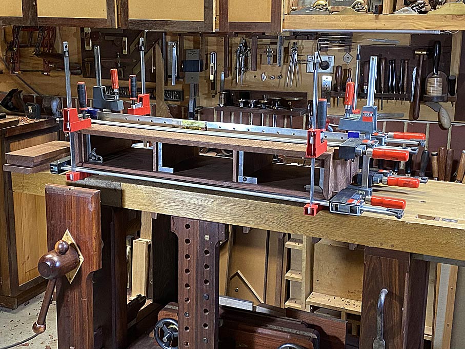
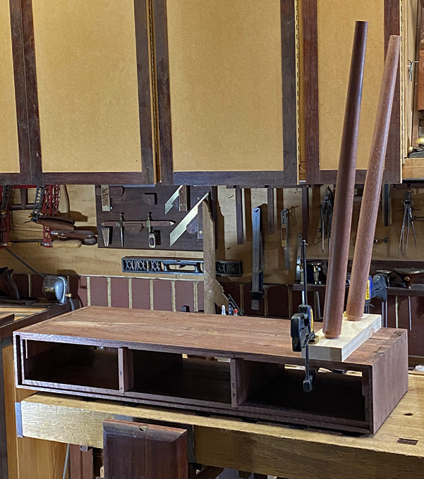
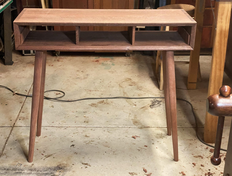
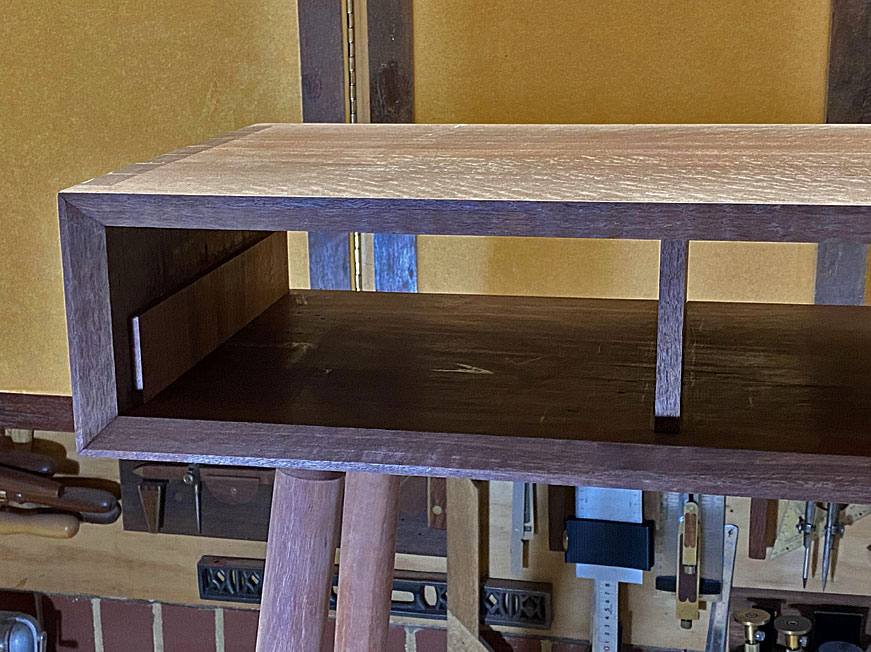
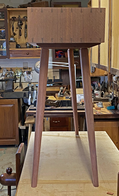
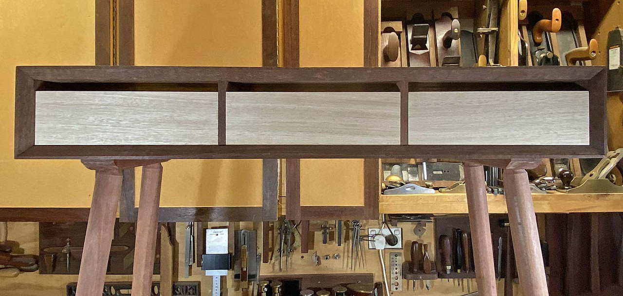
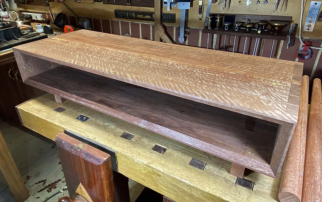
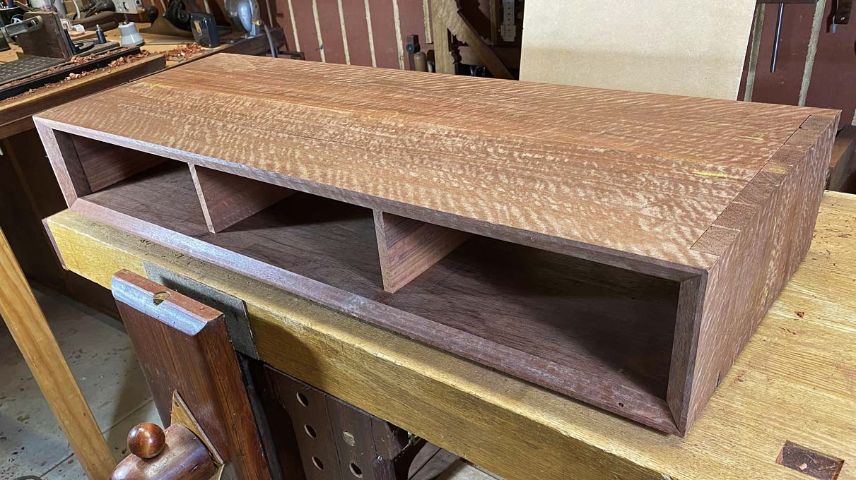
The basic case complete ...
My niece's expressed wish is to have a table front looking as if it was faced by a single board. The original model for this project has two drawers. I did not see this working here since, as their width would be greater than their depth, two drawers would likely rack. Consequently, I decided to build three drawers of equal width (I considered a narrow drawer in the centre, but decided this would be too busy).
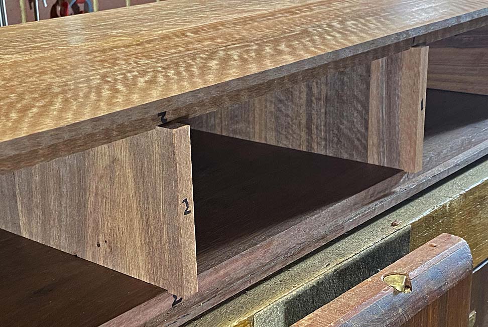
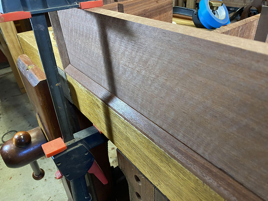
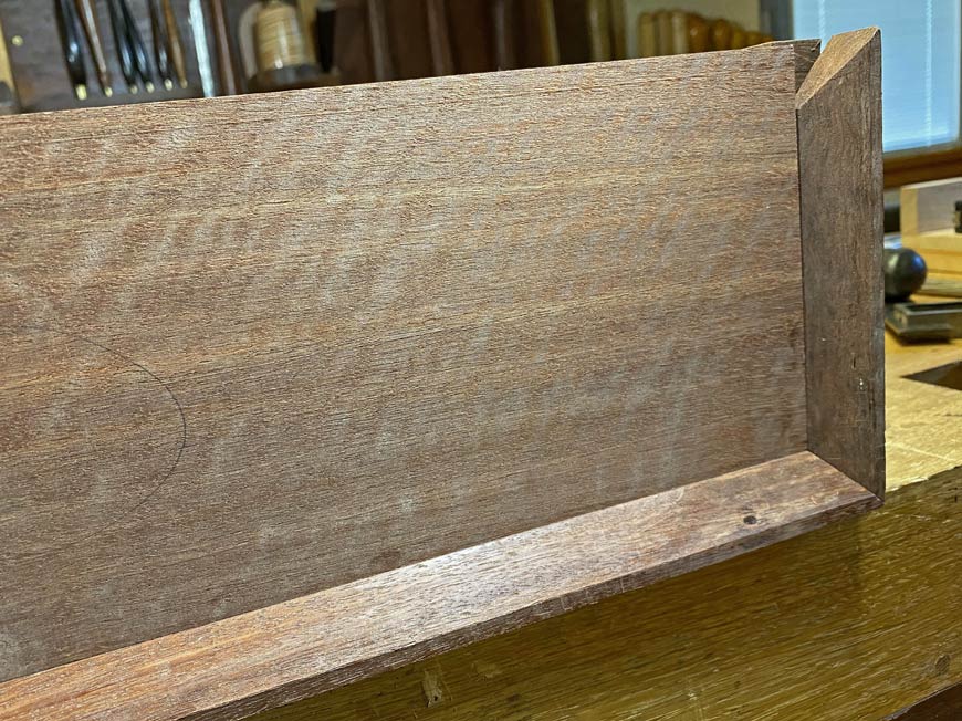
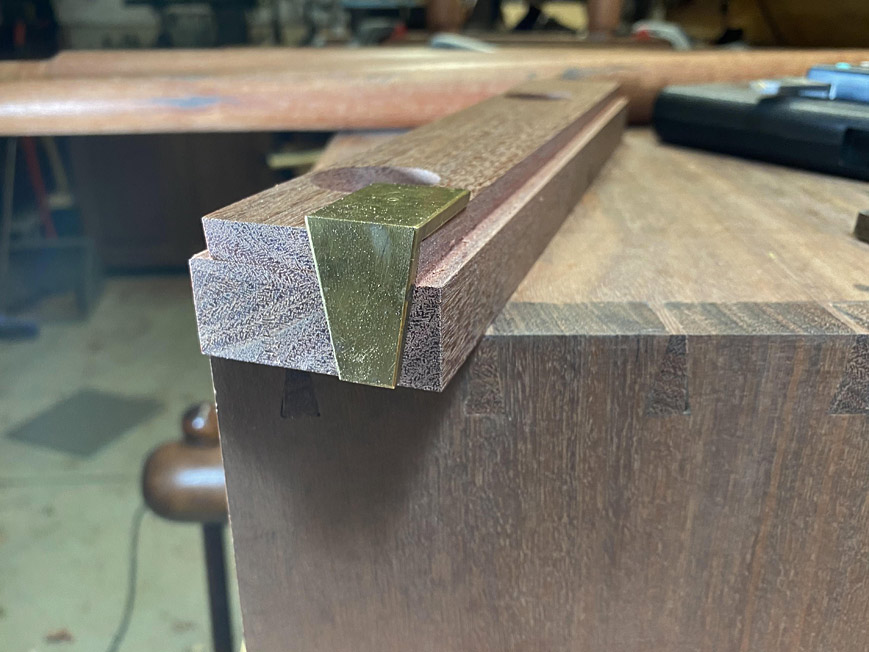
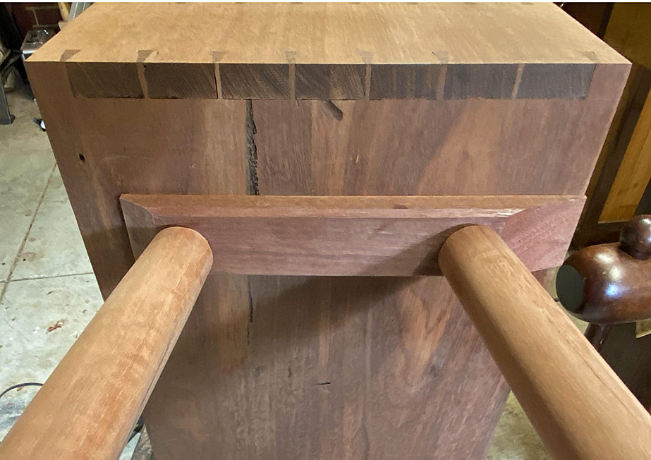
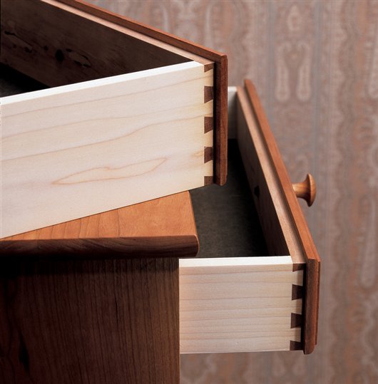
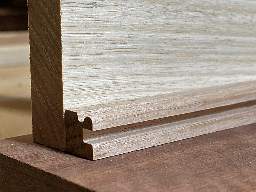
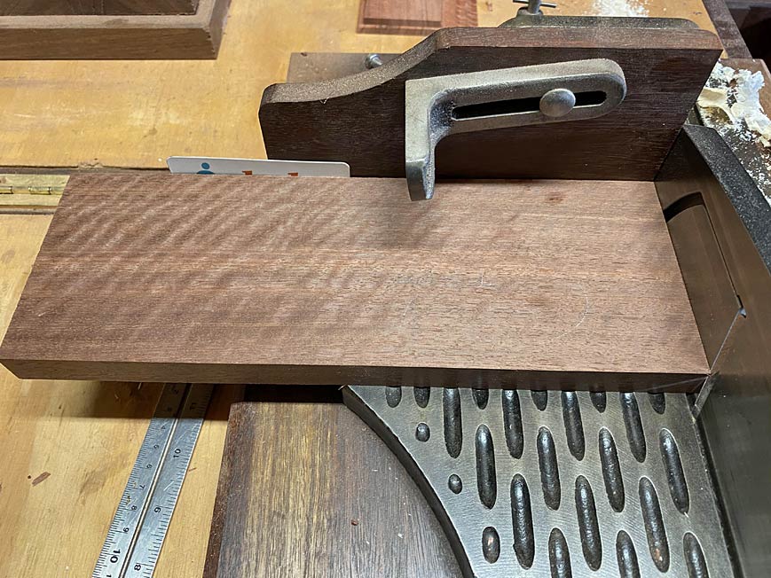
In order that the figure of the drawer fronts would not be interrupted by the drawer dividers, the drawers are to have half-blind dovetailed side lips, such as these ...
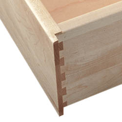
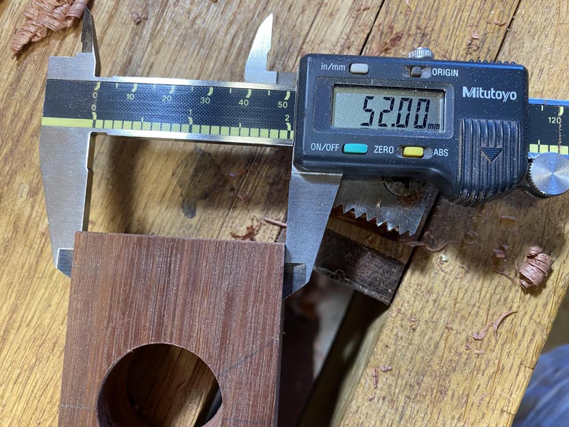
The drawers will each have a side lip of 6mm. This requires a 6mm wide side panel on each side of the case, and two 12mm wide drawer dividers. This will allow three drawers to run adjacent to one another, and the three fronts to be cut from a single board.
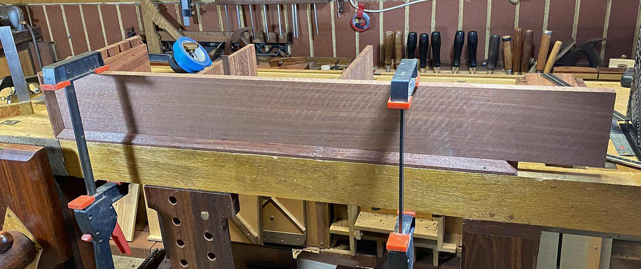
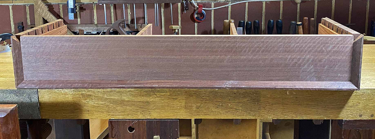
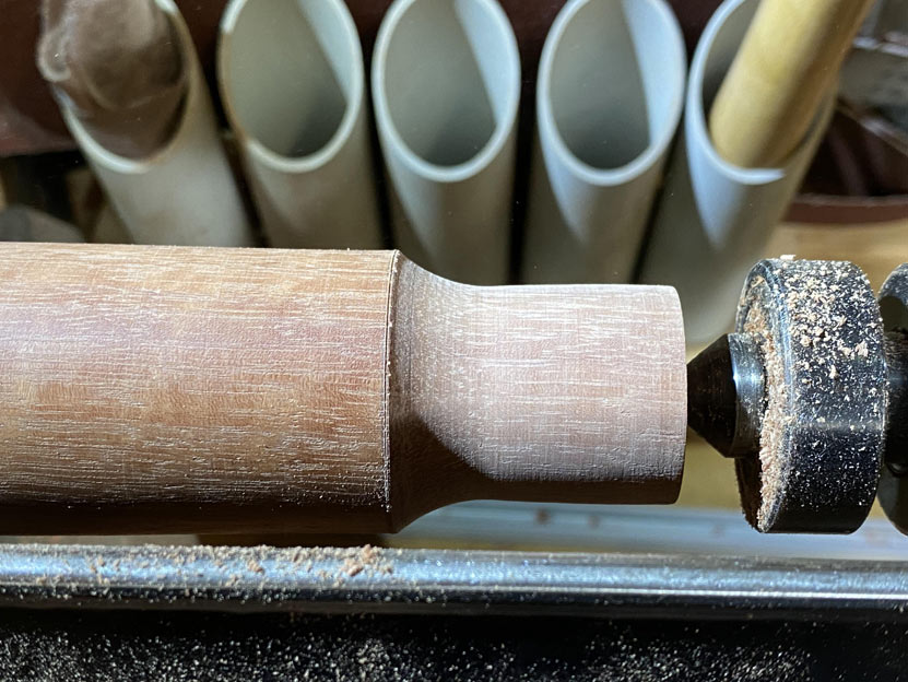
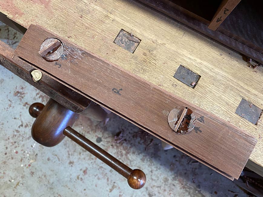
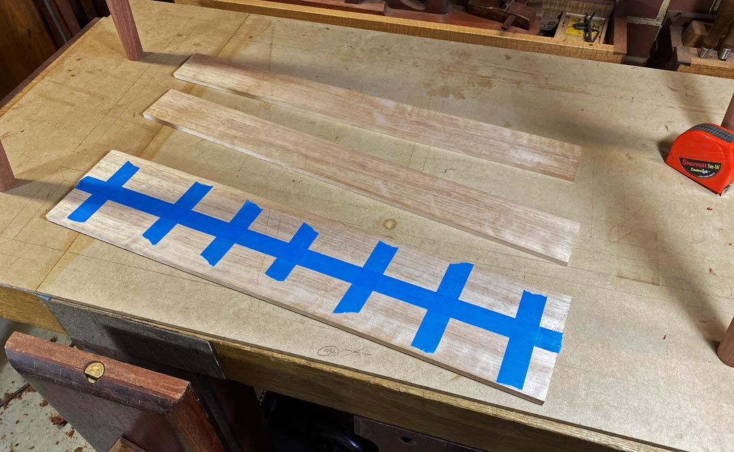
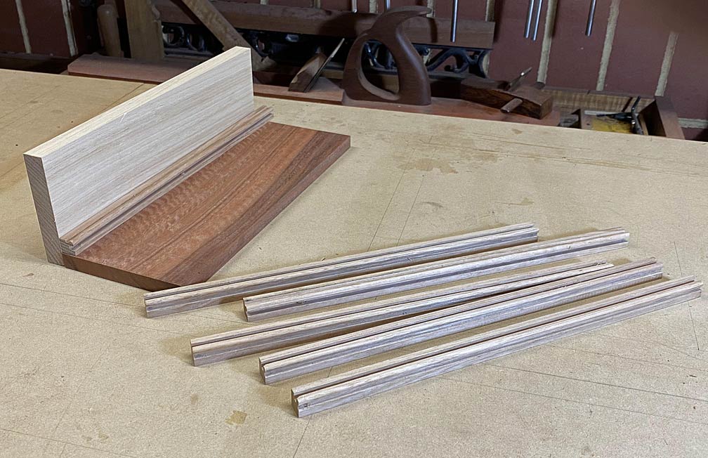
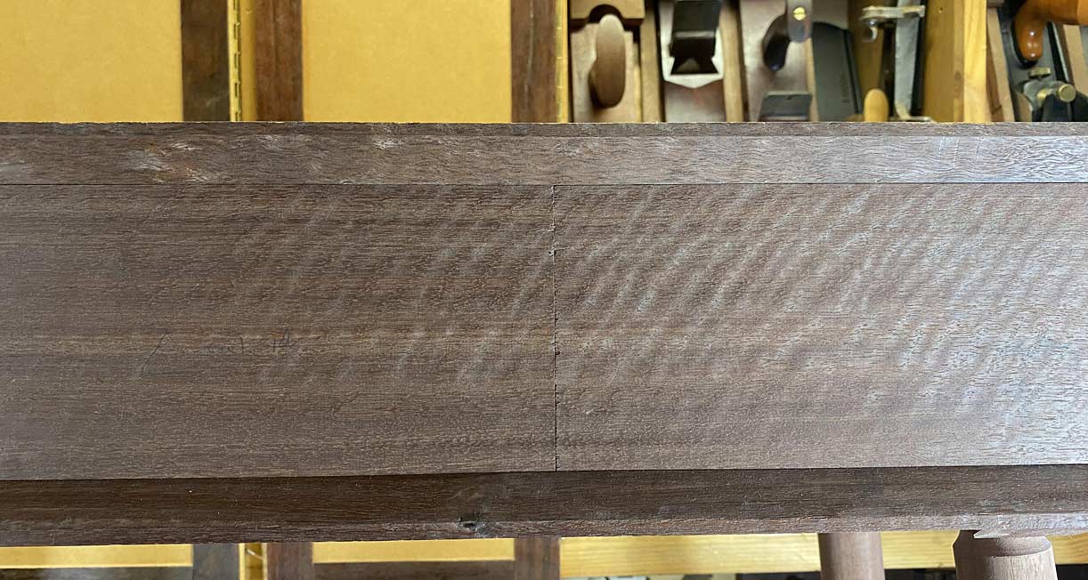
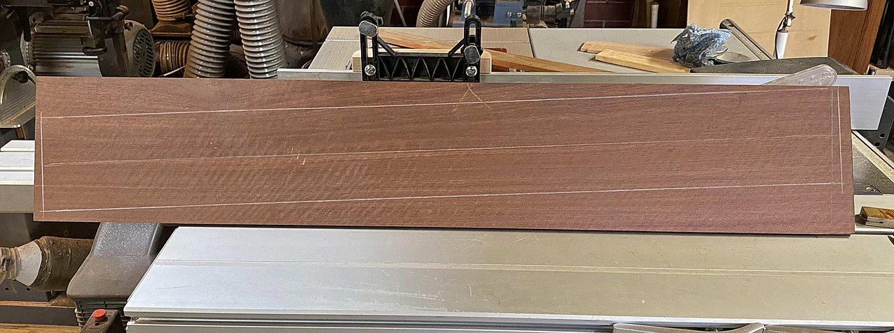
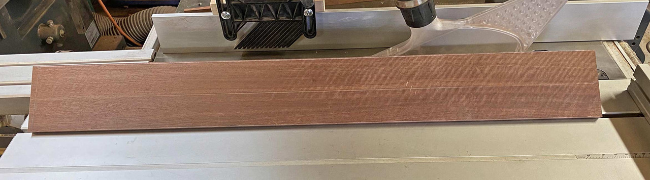
The drawer fronts will come from this board ...
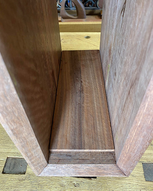
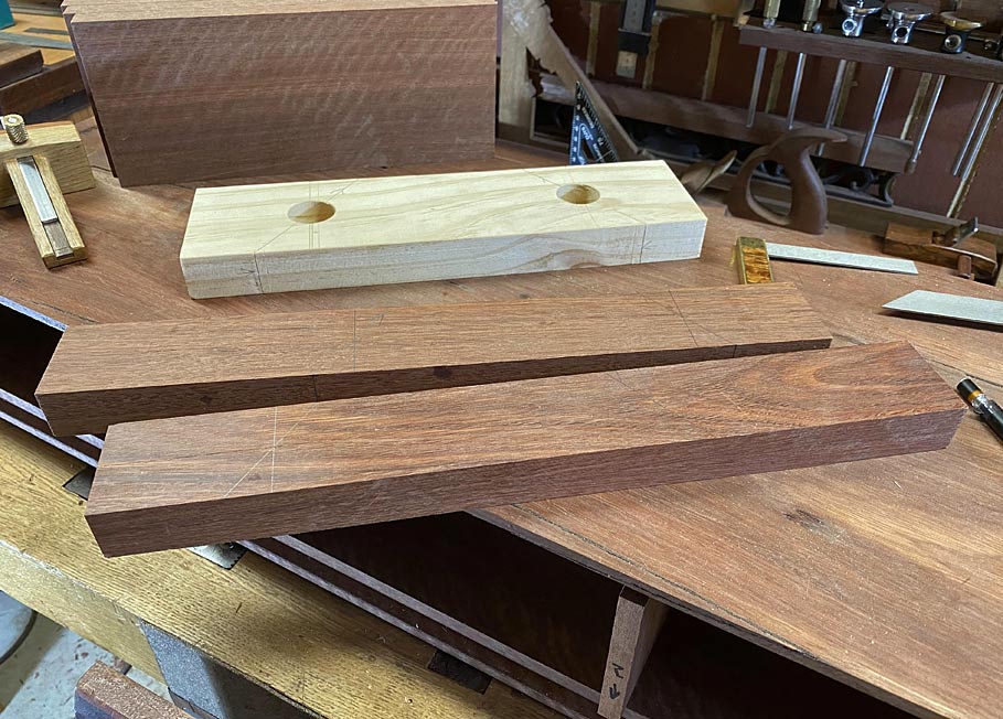
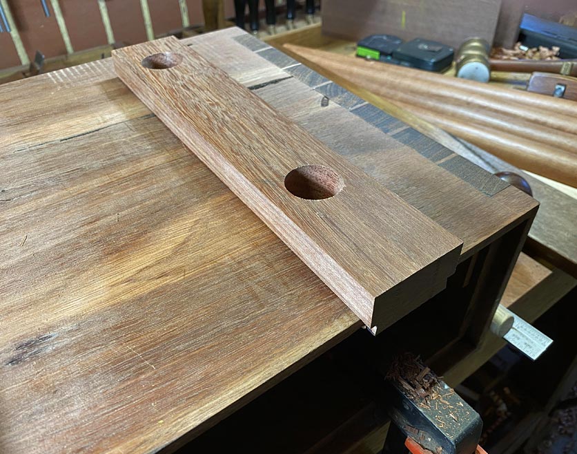
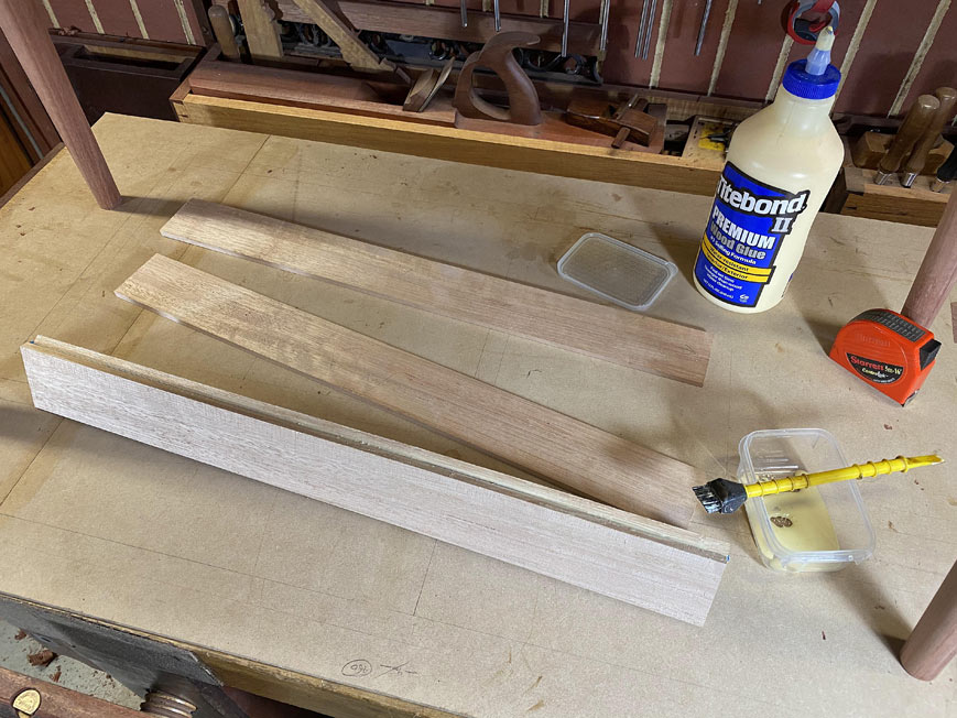
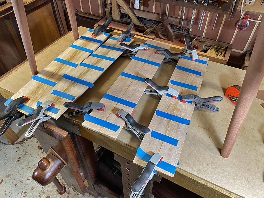
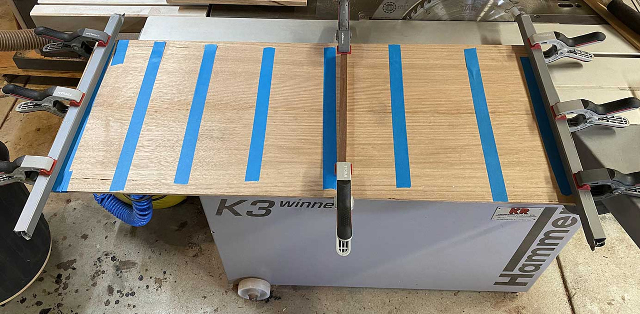
Below are the panels for fitting ...
It occurred to me later (of course!) that the 6mm end panels could have been made to run with the grain direction of the case. Being the same Jarrah, this would have counted for any expansion/contraction, and there would not be any danger of movement being intrusive. Too late. It's glued.
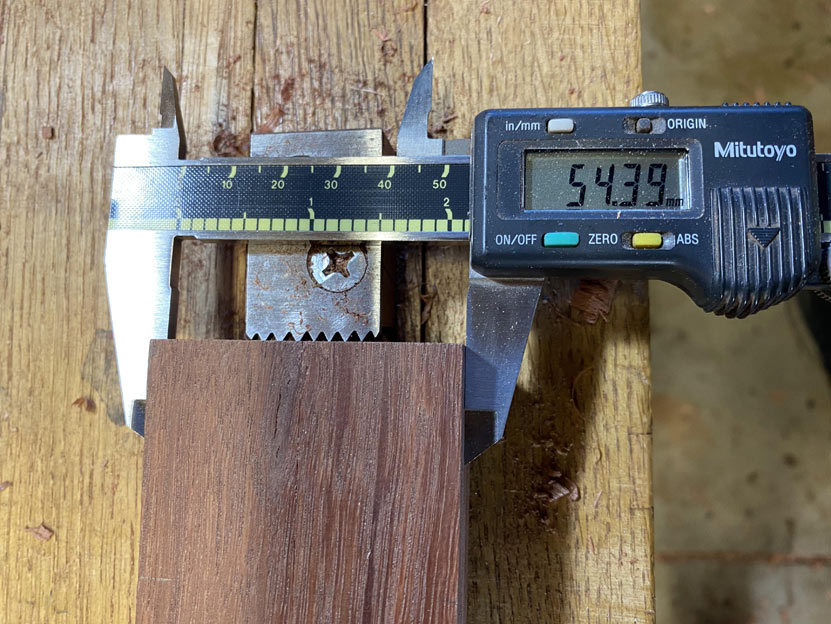
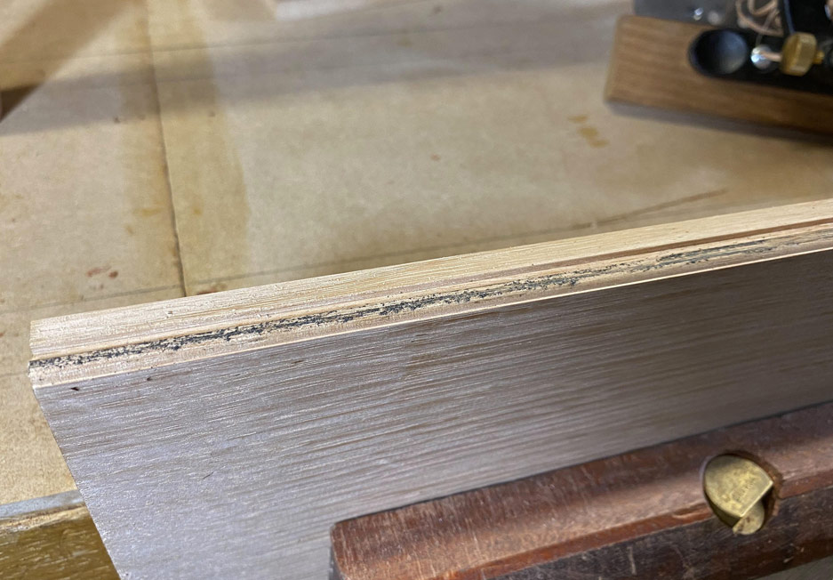
So I did the next best thing, and planed 2mm off the upper and lower edges. This will permit enough movement, if any (it is a small and thin panel). There will not be any gaps seen as the front edges will later receive edging, which will be used as a depth stop.
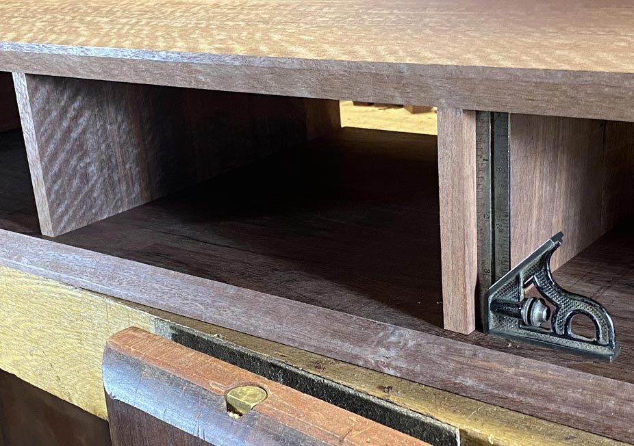
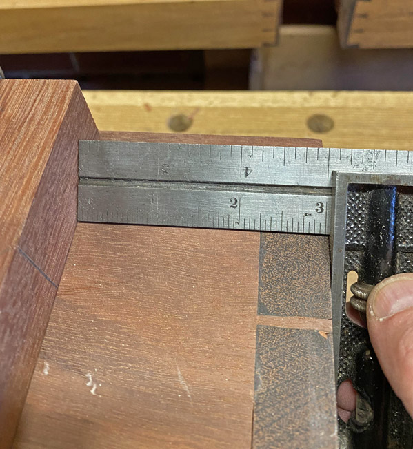
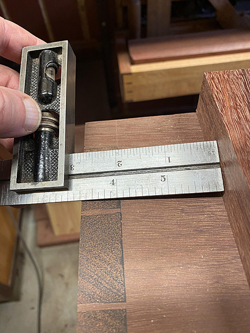
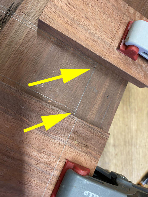
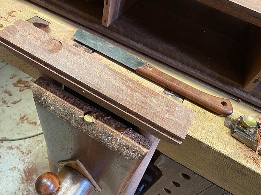
Frankly, the hardest part of this section of the project was accurate marking out of the two central drawer dividers. These need to be both perfectly parallel, and also aligned vertically (the lower panel with the upper panel).
There is a second area that needed to checked, which is important for drawers to work well, and this that the lower panel is flat - that is, does not have any hills. I learned my lesson the hard way about this. All good.
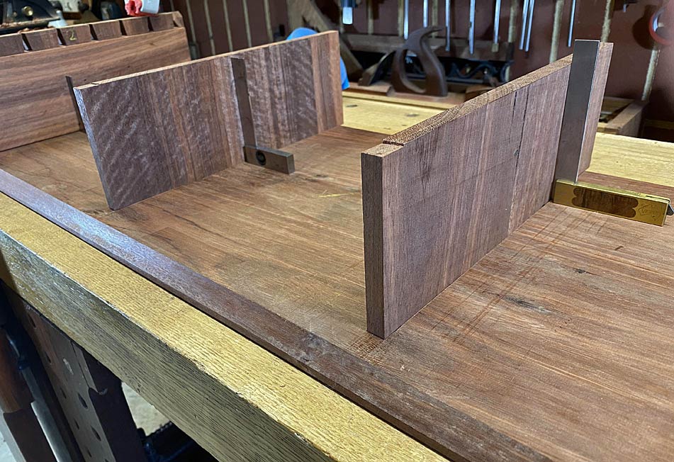
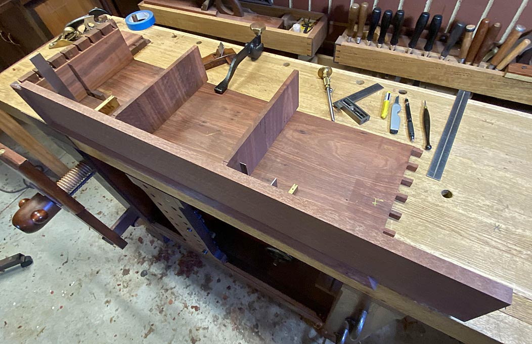
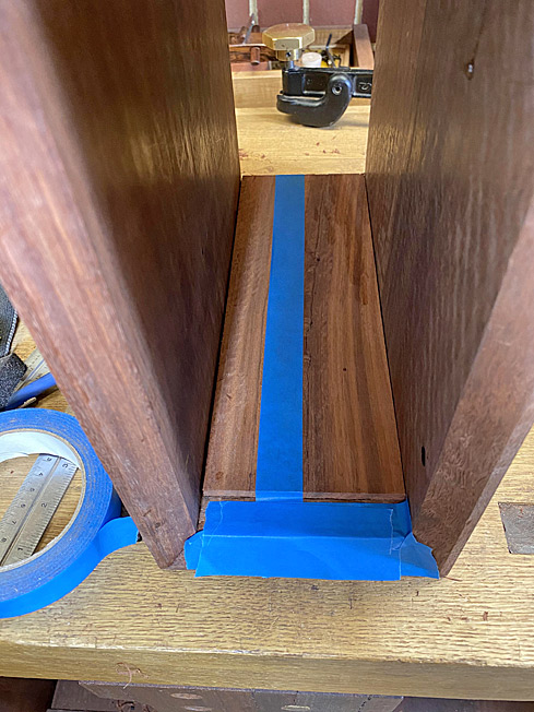
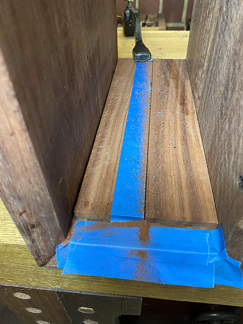
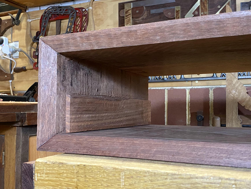
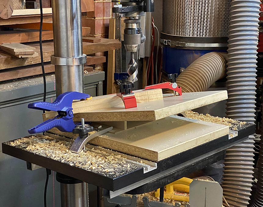
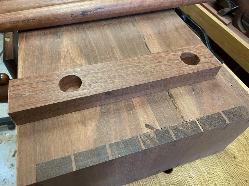
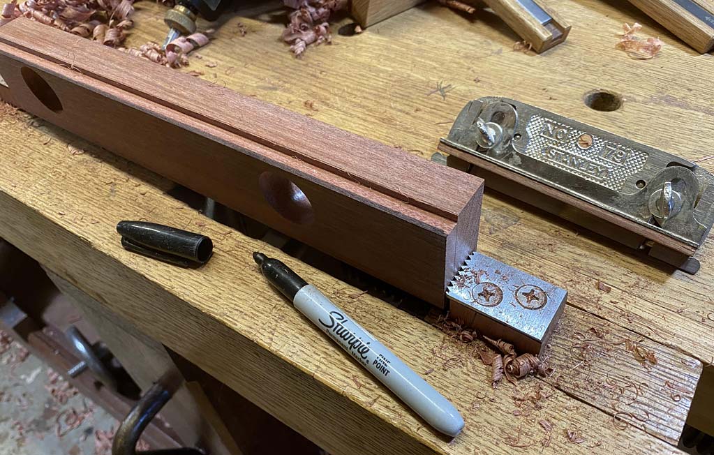
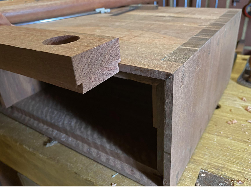
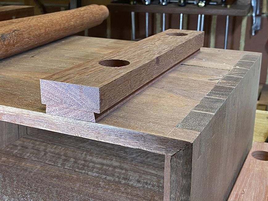
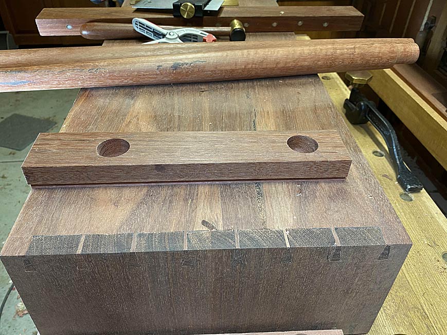
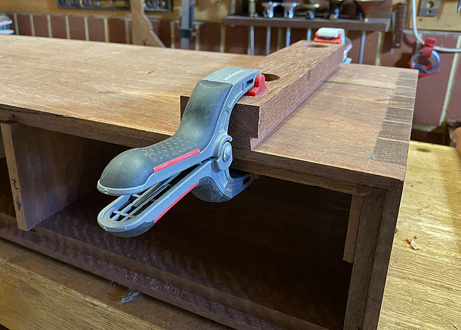
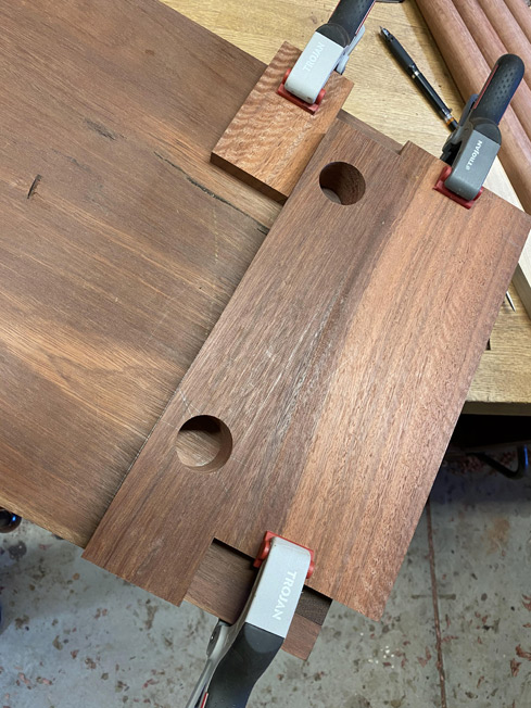
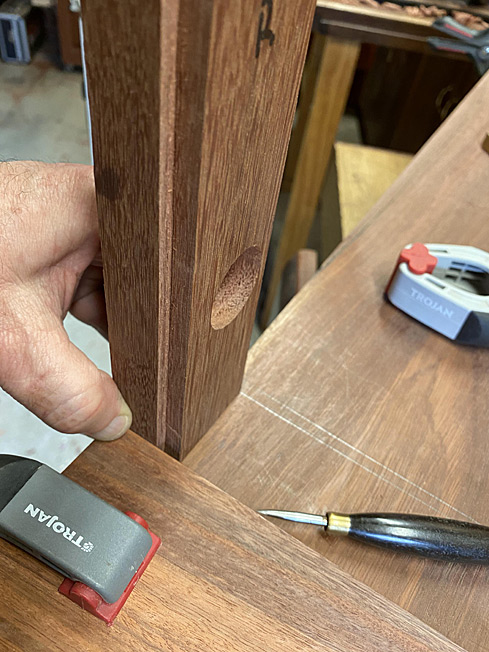
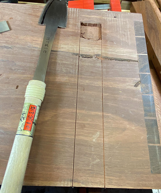
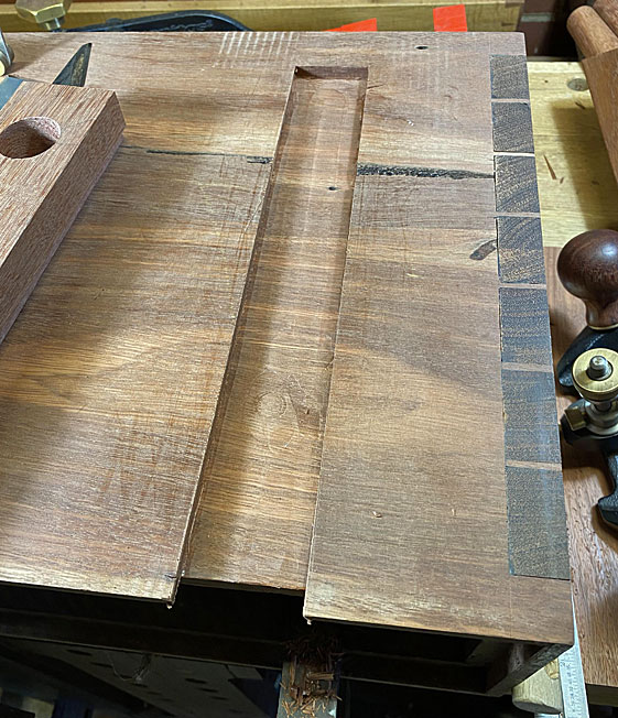
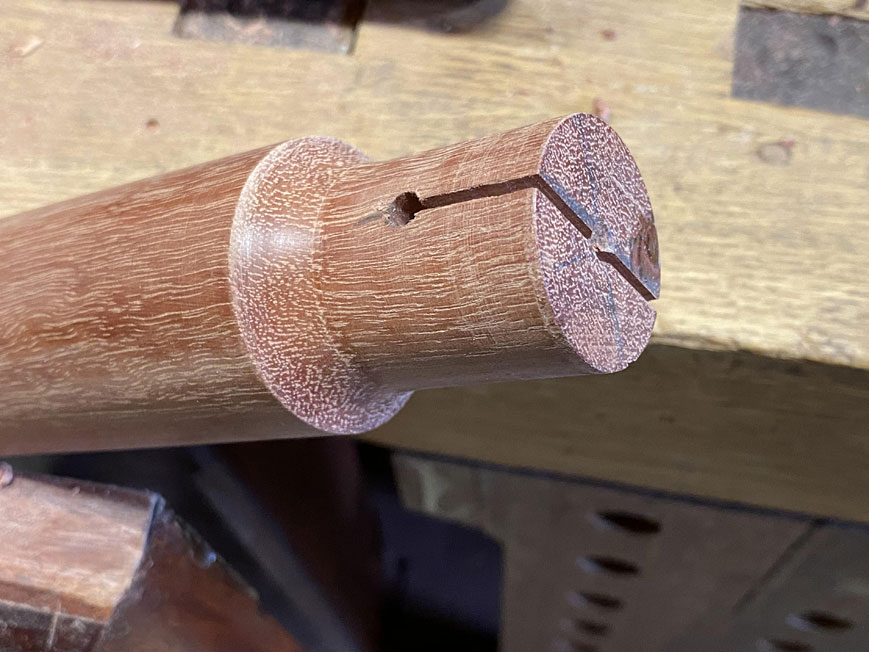
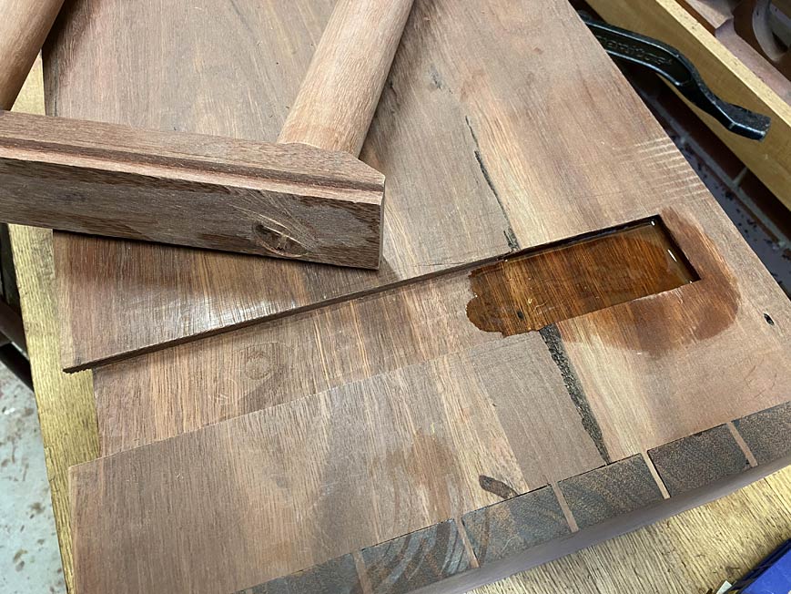
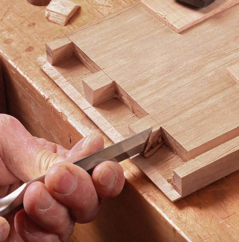
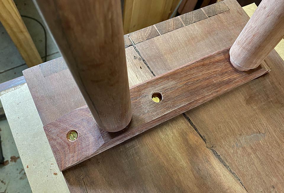
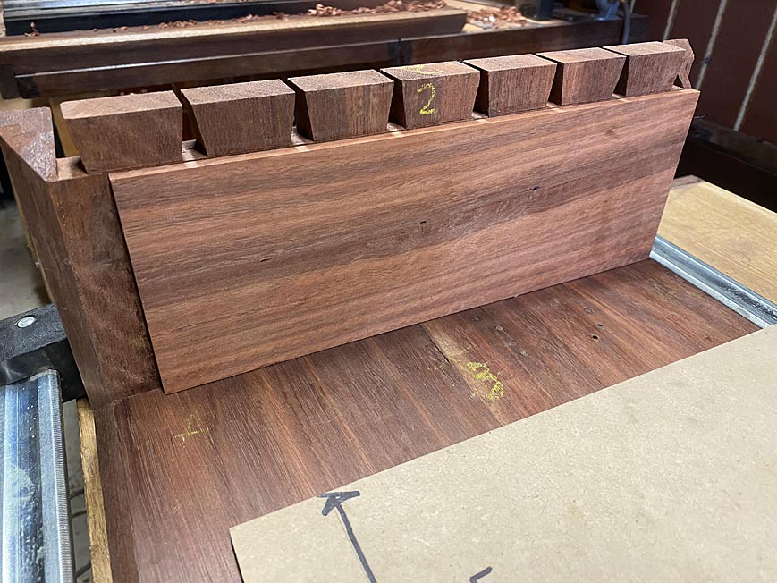
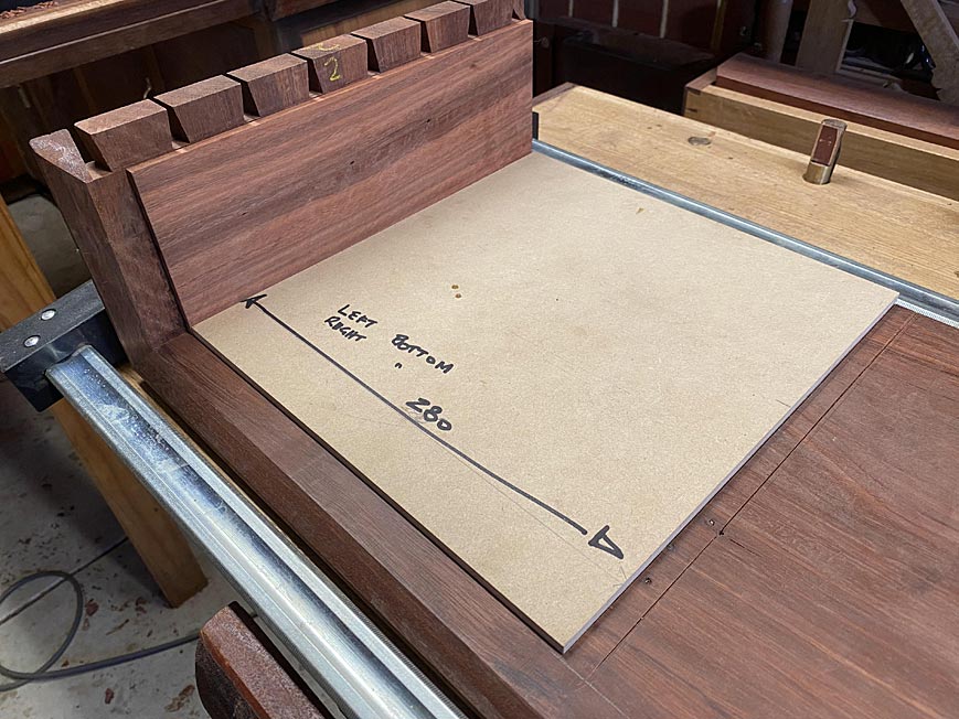
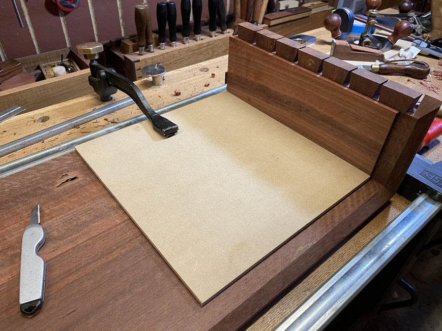
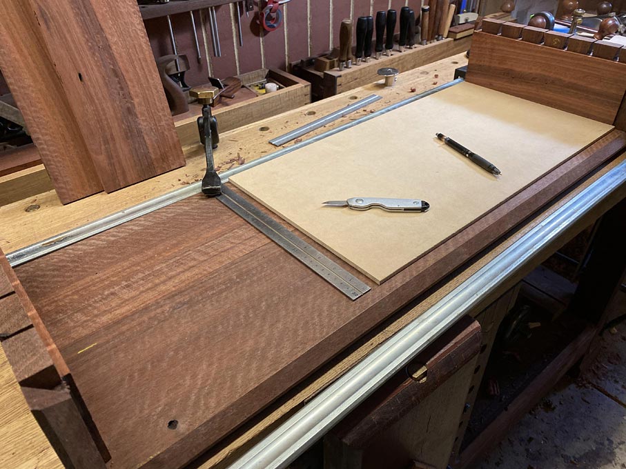
The way I go about marking the dados for the dividers is to make templates for their position. These are used on both the lower panel, as below, and then the upper panel ...
The process is self-explanatory ...

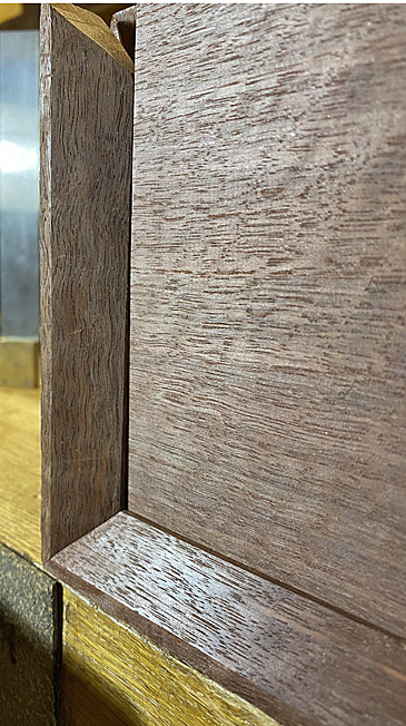
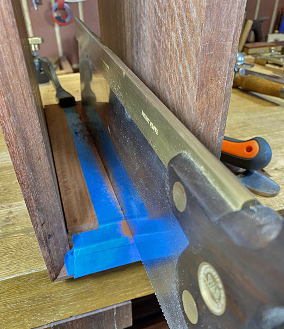
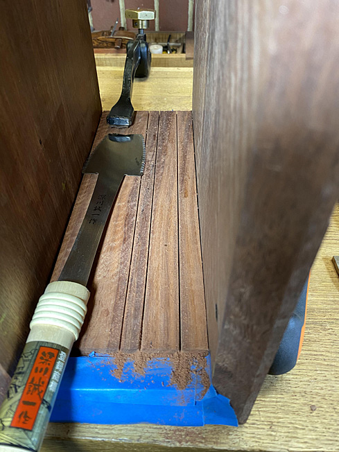
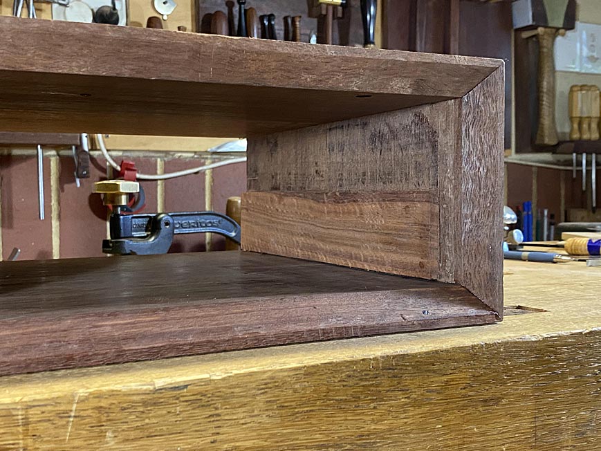
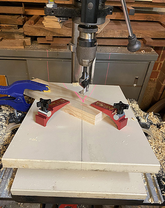
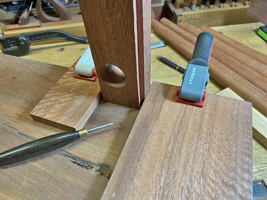
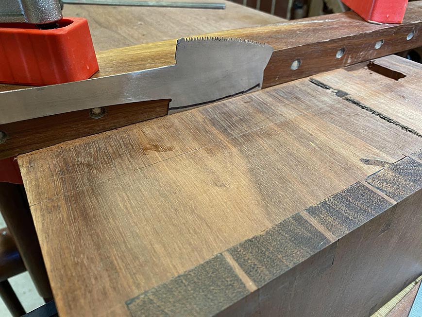
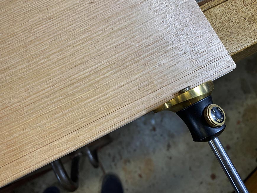
The dados are knifed deeply ...
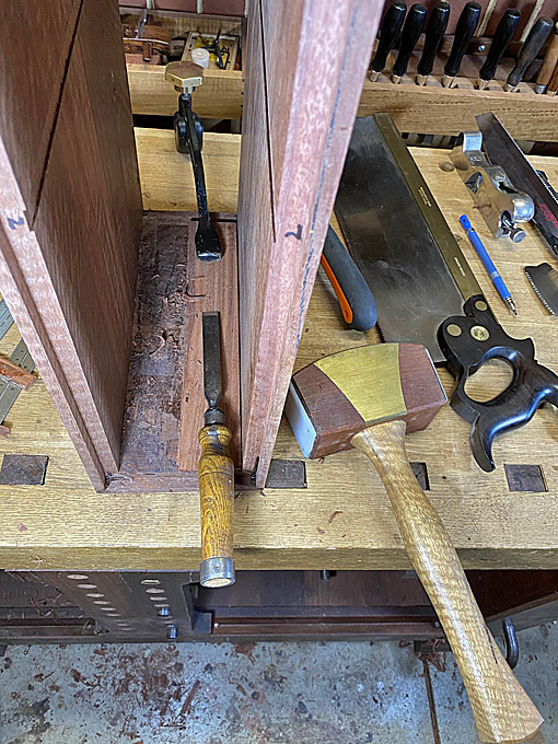
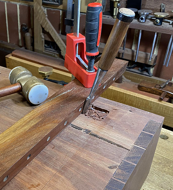
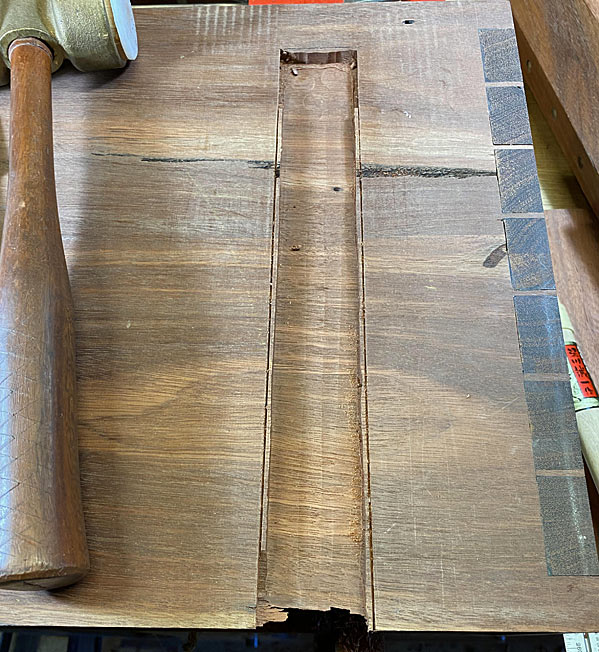
Chisel walls cut ...
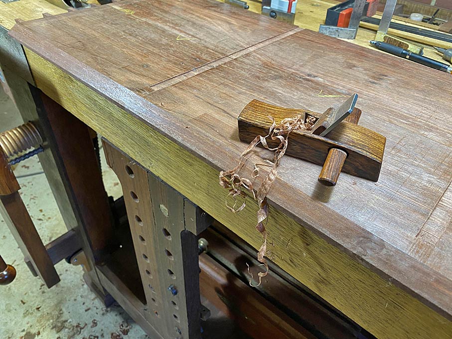
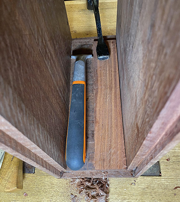
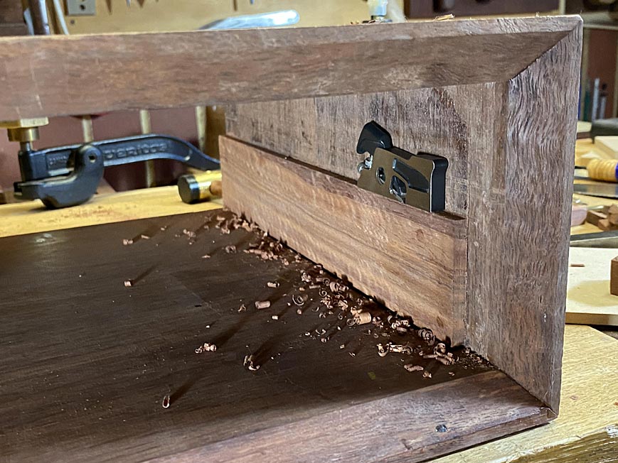
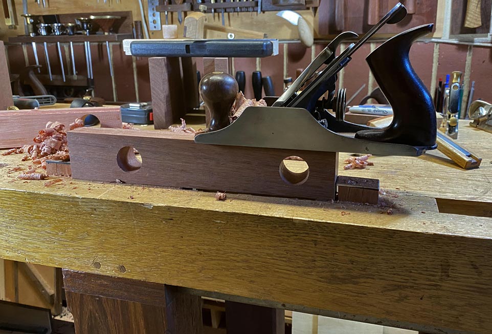
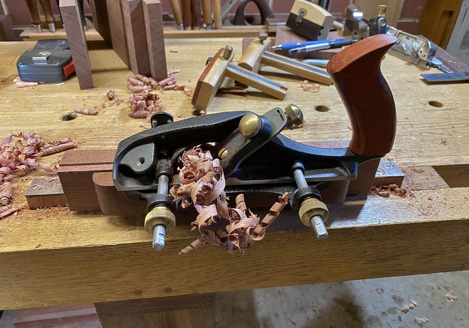
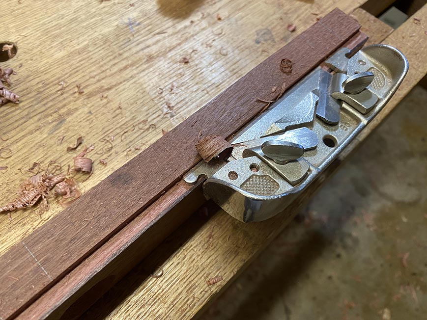
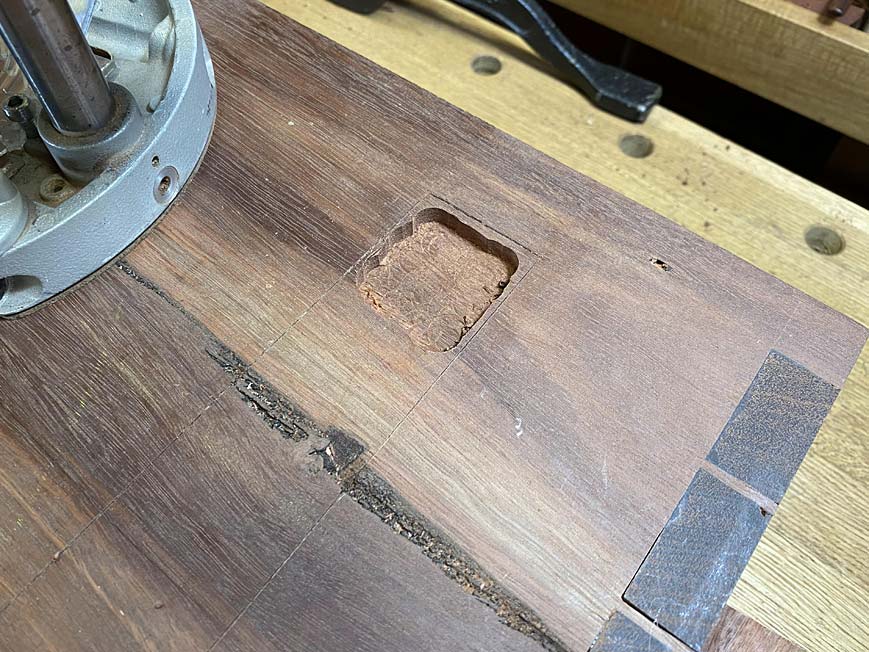
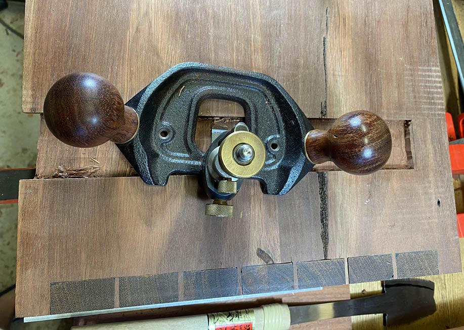
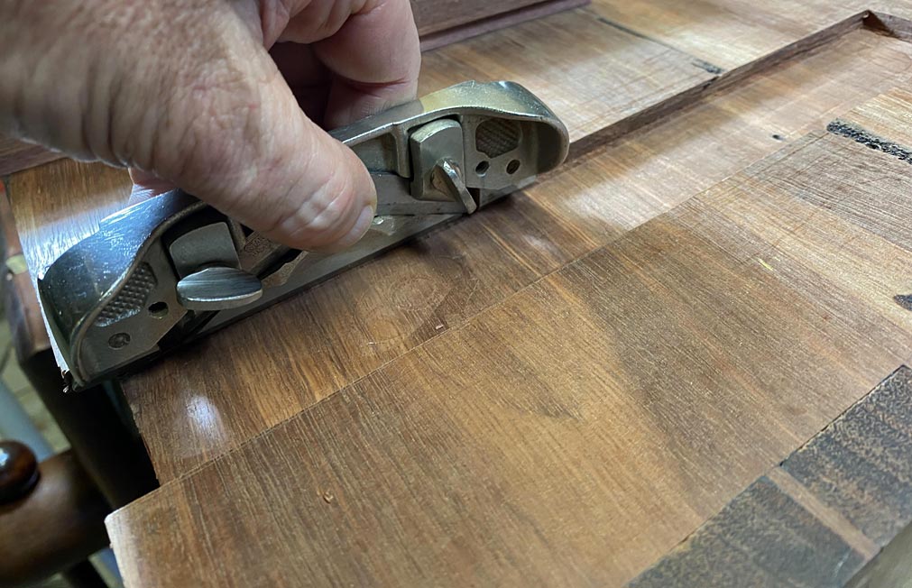
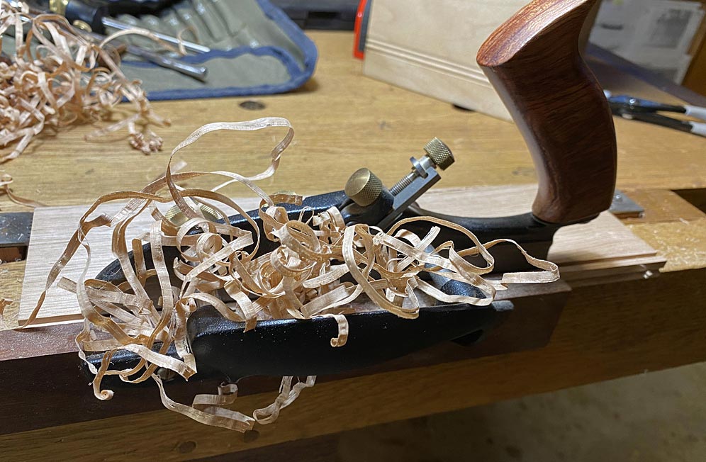
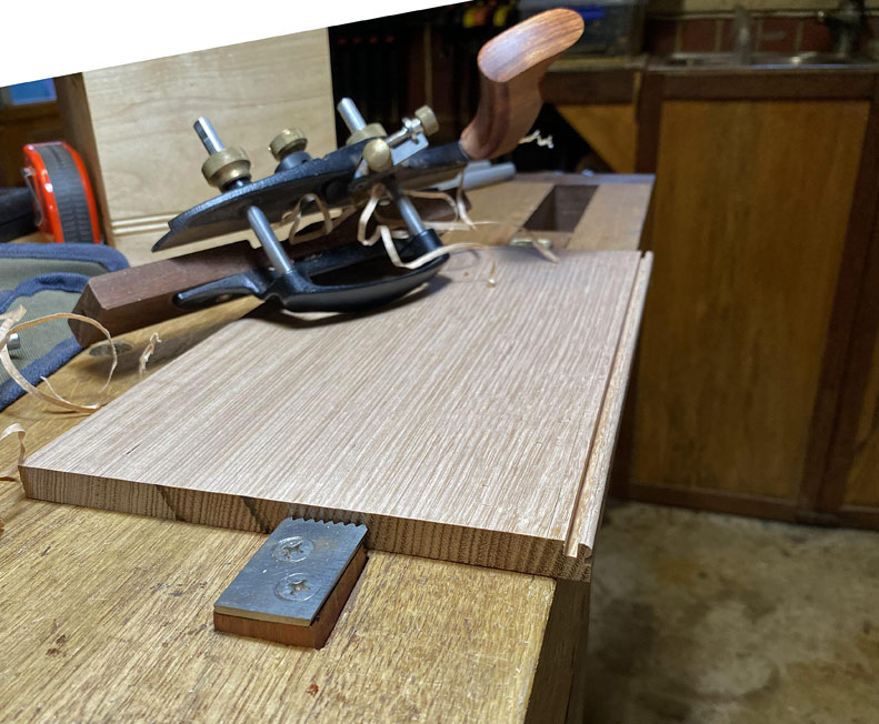
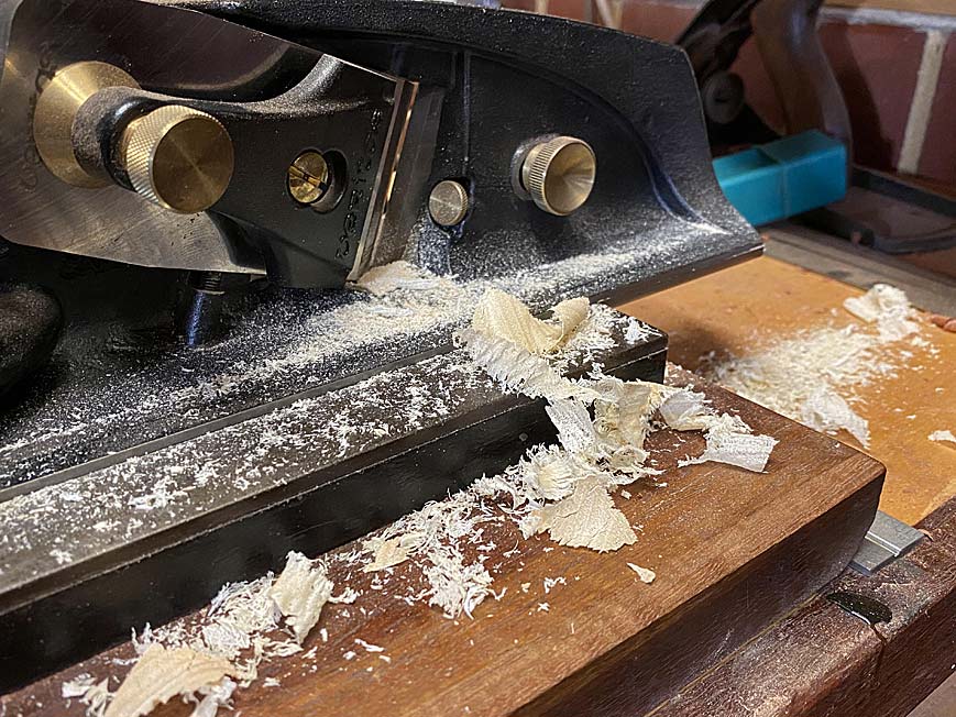
.. and then the waste is removed with a router plane ...
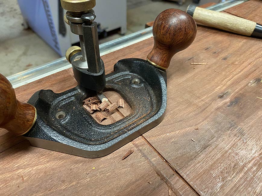
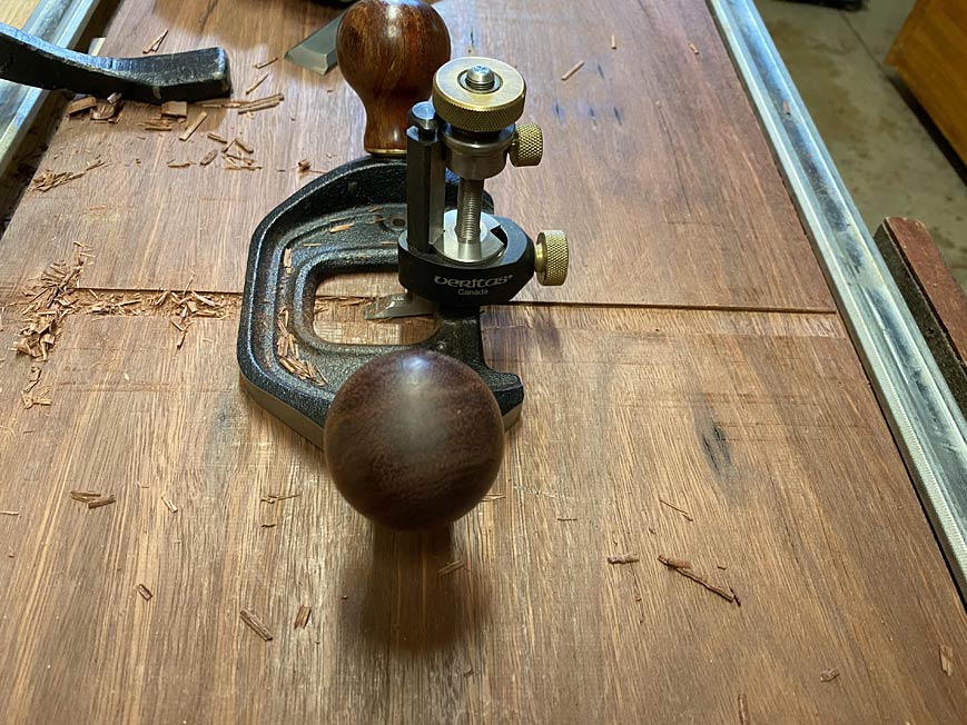
The dados are just 2mm deep. That is deep enough to prevent any movement. This process is quick and relaxing (compared to setting up and using a power router).
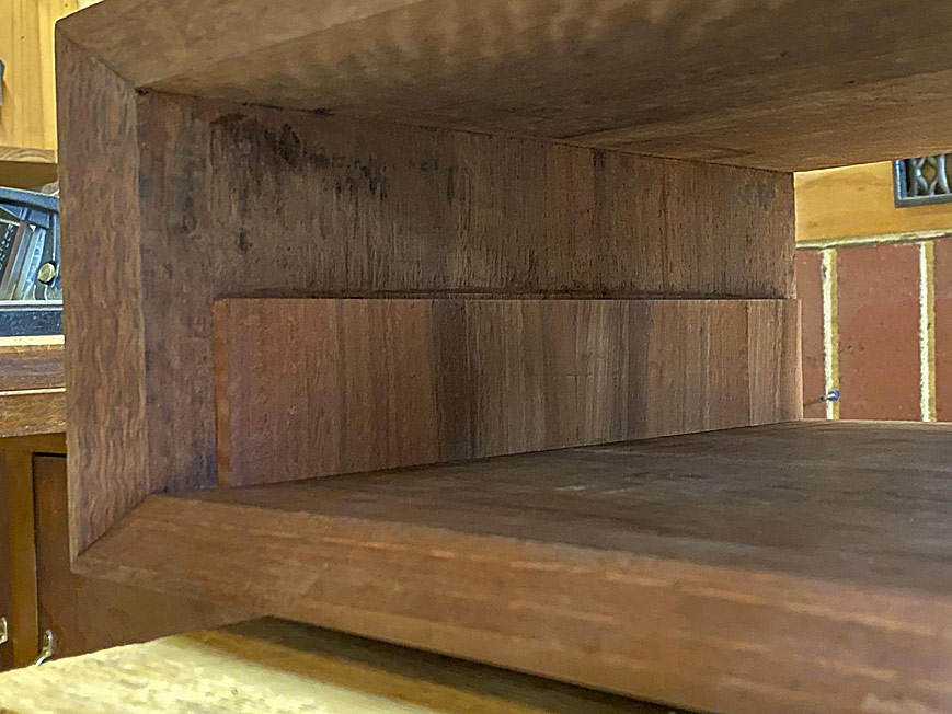
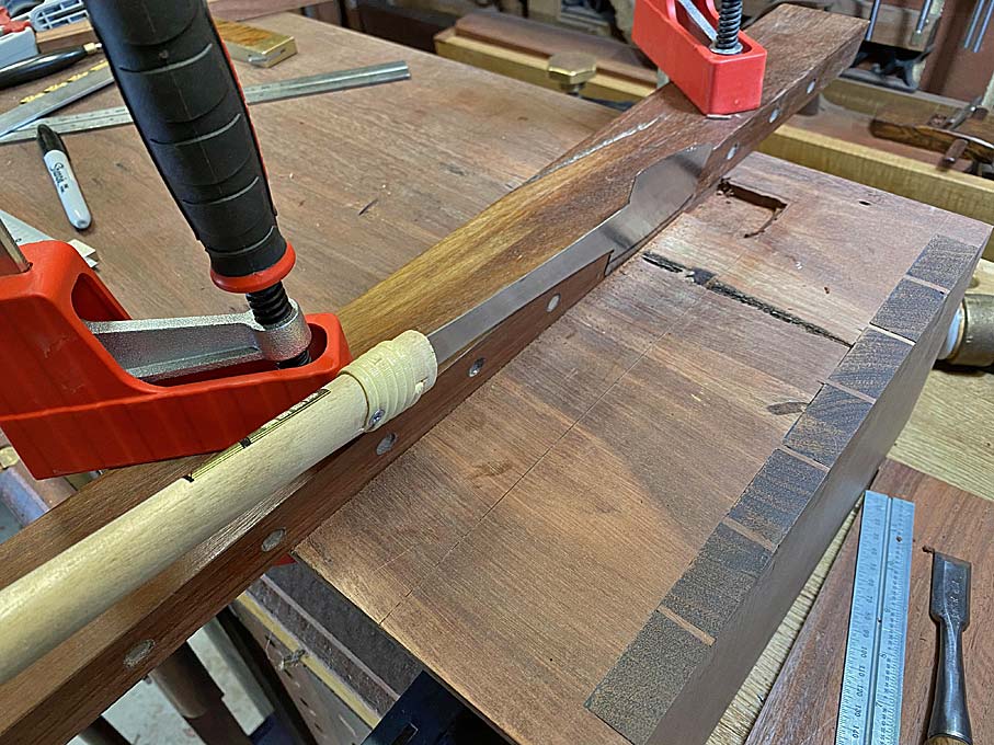
Once done, the process is repeated on the upper panel ...
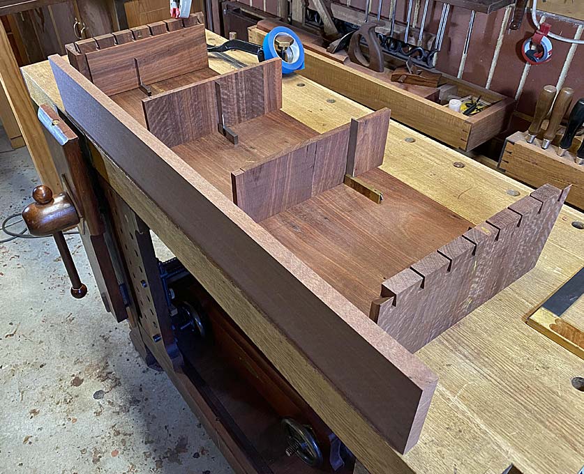
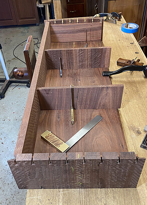
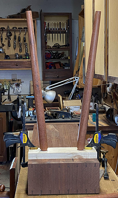
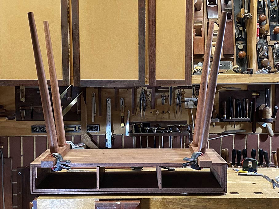
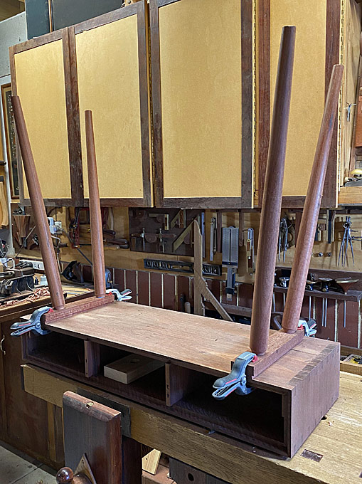
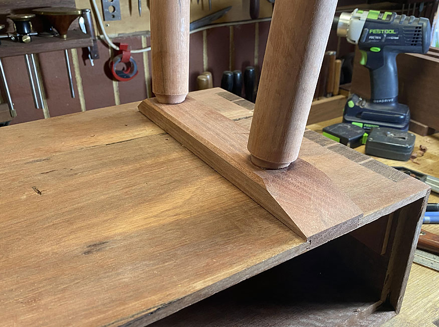
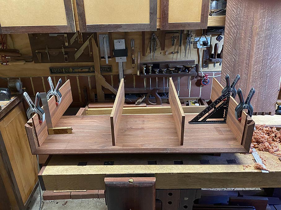
All ready for a dry fit. The rear of the case ...
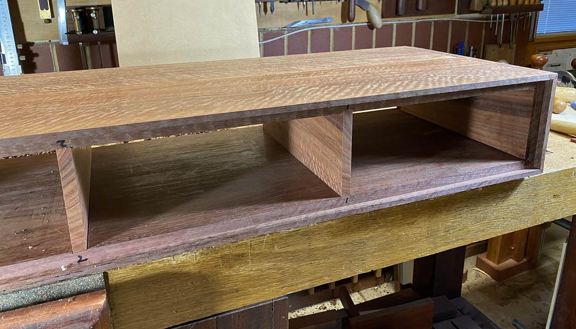
... and the front ...
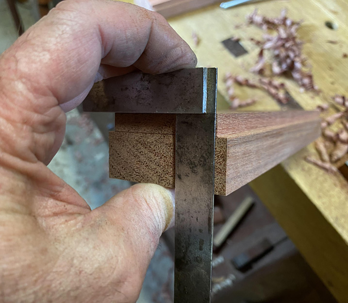
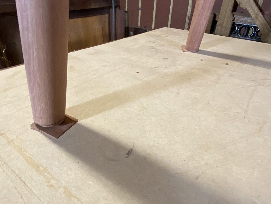
Happily, all is square ...

Tomorrow I shall glue it up.
Regards from Perth
Derek
My niece's expressed wish is to have a table front looking as if it was faced by a single board. The original model for this project has two drawers. I did not see this working here since, as their width would be greater than their depth, two drawers would likely rack. Consequently, I decided to build three drawers of equal width (I considered a narrow drawer in the centre, but decided this would be too busy).
In order that the figure of the drawer fronts would not be interrupted by the drawer dividers, the drawers are to have half-blind dovetailed side lips, such as these ...
The drawers will each have a side lip of 6mm. This requires a 6mm wide side panel on each side of the case, and two 12mm wide drawer dividers. This will allow three drawers to run adjacent to one another, and the three fronts to be cut from a single board.
The drawer fronts will come from this board ...
Below are the panels for fitting ...
It occurred to me later (of course!) that the 6mm end panels could have been made to run with the grain direction of the case. Being the same Jarrah, this would have counted for any expansion/contraction, and there would not be any danger of movement being intrusive. Too late. It's glued.
So I did the next best thing, and planed 2mm off the upper and lower edges. This will permit enough movement, if any (it is a small and thin panel). There will not be any gaps seen as the front edges will later receive edging, which will be used as a depth stop.
Frankly, the hardest part of this section of the project was accurate marking out of the two central drawer dividers. These need to be both perfectly parallel, and also aligned vertically (the lower panel with the upper panel).
There is a second area that needed to checked, which is important for drawers to work well, and this that the lower panel is flat - that is, does not have any hills. I learned my lesson the hard way about this. All good.
The way I go about marking the dados for the dividers is to make templates for their position. These are used on both the lower panel, as below, and then the upper panel ...
The process is self-explanatory ...
The dados are knifed deeply ...
Chisel walls cut ...
.. and then the waste is removed with a router plane ...
The dados are just 2mm deep. That is deep enough to prevent any movement. This process is quick and relaxing (compared to setting up and using a power router).
Once done, the process is repeated on the upper panel ...
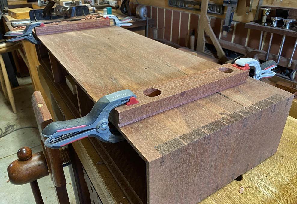
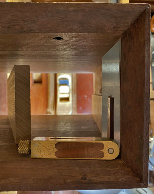
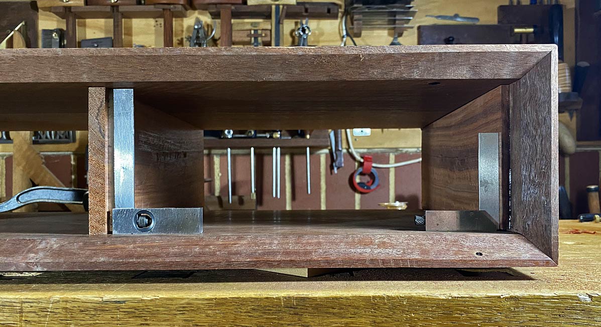
All ready for a dry fit. The rear of the case ...
... and the front ...
Happily, all is square ...
Tomorrow I shall glue it up.
Regards from Perth
Derek
")