How to guide OF 1010 properly along a curved edge?

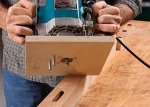
I would solve it this way (as you have a router):
  • obtain:
    • sheet of cheap sheet material (for templating)
    • one slot bit (with same diameter bearing on the shaft) sized in diameter and depth (or deeper, then as a last step you'll need to make thicker copy of the final template) to the slot you want
    • one copy/flush trim bit (with bearing sized identical to the cutter, possibly you can use the first one for this too),
    • one displacement copy bit (smaller bearing than the cutter diameter, which will lead to a smaller copy than the original) sized so the intendet inner-side displacement of the slot is a multiple of that bits displacement (difference between the bearing and cutter radius)
  • make a 1:1 template of the original (the one you want the slot in at the end) with the copy/flush-trim bit
  • fit the displacement copy bit into your router, with the height adjusted so that the cutter covers slightly over* 50% of the material thickness
  • do a pass on the template, this will make a rabbet half the material thickness
  • flip the template over and repeat the process of the last step (guiding the bearing in the rabbet from the last step) until you reached the intended inward side displacement for the slot, then do a pass with the copy/flush trim bit to complete the creation of the inward side template
  • then make a template for the outward side of the intended slot (so you'll have templates on both sides of the intended slot which will fully prevent the router from wandering off as it'll be guided on both sides) by simply running the slot bit along the inward template into another template sheet - you could skip this step but it'll ensure that you will only destroy cheap template material instead of the original should you fail to guide snugly along the inward template
  • attach the templates(s) you ended up with to the original, use the slot bit to perfectly make the slot into the original - in case your slot bit would cut to deep you need to copy the templates onto thicker material first (or make them out of thick enough material in the first place)

EDIT: Hopefully clarified it a bit and added an outward template to the procedure, drop me a line in case you need a drawing to wrap your head around the concept (it is a recursive variation of templating for inlays).
In case you have a shaft mounted ball bearing bit that can be used for slotting where you can change the bearing and the cutter diameter is big enough so you can fit smaller one: you could get away with only that one bit (and two bearings, one same size to cutter and a smaller one), but having a higher displacement will speed up the process (by reducing the amount of passes you need to make on the template) and save quite some time (and reduce wear on the bit as of less passes).

EDIT: * exactly 50% is not needed, slightly over is enough. Modified the howto in that regard.
 
That's a good how to video , but it's not applicable here at all.

shu's post on Oct. 19  will explain why.
 
antss said:
That's a good how to video , but it's not applicable here at all.
Actually it applies, as it shows the offsetting action - just with a face displacement that adds material on the processed piece (relative to the template) instead of removing it as I suggested one post above his.
 
Well,  it applies if you want say he's using a router and a template too.  I could post a how to on using a starting pin on a table and say " hey  this might help too " .  But it won't really.

The type of cut shu want to make can't be made on a router table very easily. Shu's piece is waaaaaaaay too big for starters. Being on the face instead of the edge is another problem for applying the video tips.

So , I will stand by my statement that the video really isn't very helpful for this project.
 
[member=21249]RKA[/member]

Thank you. I may explore other method first for the simple reason that I may only do this kind of curve slot once. So if I have to buy something, I wish I can use it elsewhere.

[member=978]Dongar[/member]

Thanks. The video actually solves me another issue as I need to produce a negative curved thin MDF to cover the part of wall that's not covered by the plywood.

[member=53905]Gregor[/member],

Thanks for your step by step instruction. I do need a rough sketch to understand it if possible. Thanks in advance. I only have a 6mm straight bit without any bearing for this task. Can I install a bearing on the straight bit?

[member=727]antss[/member],

Yes, my piece are way too heavy as well. The largest piece is 2400mm long and 1200mm tall, with 25mm in thickness. It would be even difficult to flip it over.

[member=297]Michael Kellough[/member],

Is there any video or illustration I can use to understand [member=5277]Alex[/member]'s two pin method?
 
antss said:
Well,  it applies if you want say he's using a router and a template too.
He asked for a way to locate the slot ~30mm away from the curve he made, in a controlled manner, presumably with an OF 1010.
The type of cut shu want to make can't be made on a router table very easily.
But with the router handheld and the piece on the table (or some other support, even on the ground), so the size of the workpiece dosn't matter.
the video really isn't very helpful for this project
The video shows (among others) how to employ a router (and a template) to displace an edge (in- or outward) evenly over the whole length of it, regardless of that edge being straight or not.

shu said:
[member=53905]Gregor[/member],
Thanks for your step by step instruction. I do need a rough sketch to understand it if possible.
Will prepare you one later today.
I only have a 6mm straight bit without any bearing for this task. Can I install a bearing on the straight bit?
I would suggest to get something like this (randomly picked from a google search, just to show how these look) to do all sorts of router based template work and something like this (again randomly picked for the looks) to make the final slot.

While you could also DIY a bearing onto your 6mm bit you'll need a bigger diameter cutter than the bearing to locate the edge toward the inside, this won't be possibly with the 6mm bit (and the wear on it when removing 30+mm material, even with several passes, would be immense).
Yes, my piece are way too heavy as well. The largest piece is 2400mm long and 1200mm tall, with 25mm in thickness. I would be even difficult to flip it over.
Won't be an issue, as you would only need to flip the template you create (which can be made from thinner, lighter material and thus be easier to handle).
 

Attachments

.

He asked for a way to locate the slot ~30mm away from the curve he made, in a controlled manner, presumably with an OF 1010.
Quote

    But with the router handheld and the piece on the table (or some other support, even on the ground), so the size of the workpiece dosn't matter.
Quote

The video shows (among others) how to employ a router (and a template) to displace an edge (in- or outward) evenly over the whole length of it, regardless of that edge being straight or not.

Shu started this thread by asking how to put a slot on a face of a board with a curved edge.  Not how to actually make a curved edge !  That's a whole different animal than what is in the video.  Shu doesn't want to displace and edge at all.  He merely wants to follow one he already has.

Now, a large template is one way to do what shu wants -  and that has been suggested already.  He could also purchase the CMT jig suggested that would be faster and reusable and easier to handle.  But again, none of which will be done on a router table with any amount of safety.

Shu's project is going to need to be done with a handheld router.
 
[member=66123]shu[/member] corrected PDF attached.

[member=727]antss[/member]:
As you're the only one who brings up 'router table' I'm at a loss about what your point might be. Stuff might have been lost in translation (as I'm no native speaker), but I get your hint that I'm just an offtopic idiot that tried to help but failed miserably.
So I'll just stop. Sorry for distracting.
 

Attachments

Holmz said:
Some Milky/translucent plexiglass cover over the LEDs.

Exactly...this is what I'm doing for some built-in cabinets. The translucent cover does a great job in reducing the individual LED "spotlight" effect. Most of the strip LED suppliers offer these covers in different widths and lengths.

The 2nd photo gives you an idea on how even the LED beam spread is with the cover in place.
 

Attachments

  • 4503.JPG
    4503.JPG
    2.2 MB · Views: 433
  • 4418.JPG
    4418.JPG
    826.8 KB · Views: 381
[member=53905]Gregor[/member],
Thanks so very much for the impressive illustrations. The solution is very straightforward and easy to follow. Are the template bits set in your link the only thing I need to buy?

[member=727]antss[/member],
Thanks a lot for helping others understanding my questions!

[member=44099]Cheese[/member],
Thanks. I do prepare to try a cover if the test result is not ideal.

 
Gregor , your solution is very elegant , drawings through and your English is much better than my Deutch.

It has a too many steps and requires too much material for my tastes though.

The sub base and pin method Alex and I suggest requires less steps, material , and router bits to accomplish.  Even the  CMT flex template and a mortise bit would be less complicated.

What matters though, is what shu finds to be most effective.  He seems to have reservations about guiding the router along the edge with an index pin(s).  So if your way with all the templates and router bits gets him to the finished project , it's a good one.
 
Michael Kellough said:
shu said:
It seems the bit set is 1/2" which can not be used on 1010.

Am I looking at something like this?

Try this rabbeting bit set from Lee Valley. It has an 8mm shank.
Yes, something like that would do in case it enables the dimensions you need.
As I wrote:  the ones I linked were just to show how these kind of bits look - as I have no clue how these are named across the ocean and which places sell ones that last while not being overpriced... I just used a google image search.

A full set with a thin bit, a thick bit and a pile of different sized bearings might be interesting in case you plan to do more template work in the future, as such one allows to create and manipulate a wide range of templates (creating positive/negative ones for inserts, perfectly joining two kinds of wood along a non-straight seam, other fun stuff).
 
shu said:
[member=297]Michael Kellough[/member],

Is there any video or illustration I can use to understand [member=5277]Alex[/member]'s two pin method?

Why ask Michael and not Alex? Hm.  [scratch chin]

[attachimg=2]

[attachimg=1]

Shopped this together with a pic I found on the net. The two pins on the base will let you follow any curve.

The steeper the curve the closer the pins need to be together. With a smoother curve you can space them a bit wider for better stability.

Just take it slowly when you work and make sure both pins stay in contact with the edge. Since the slot is completely hidden you don't need to worry too much about precision.
 

Attachments

  • Pins-2.jpg
    Pins-2.jpg
    4.1 KB · Views: 250
  • Pin-images2.jpg
    Pin-images2.jpg
    62.6 KB · Views: 258
Since the slot is completely hidden you don't need to worry too much about precision.

When the question first came up I was thinking this was for a shelf where you could see the slot when installed.  Now knowing that isn't the case , I'd probably just mark a line 30mm off the edge and free hand the groove.

Won't be as neat as one of these other methods, but it'll be done in an hour and ready to install lights.
 
[member=5277]Alex[/member],

Thanks a lot for the photo and explanation. I now fully understand what the two pin means.

[member=727]antss[/member]

I'd eager to learn and explore all possible solutions.
If I have conservation, my only concern is:
If the distance between the bit and the line connecting the two pins is fixed(we call it A), the setback of the cut slot to the edge depends on the shape of the curve. If it's convex, the setback will be shorter; if concave, longer. And the more curvature, the more difference.

As the change of the curve is consistent, I have no way to change the distance A accordingly. Therefore I will end up have a slot that never parallels to the original curved edge.

PS. I told a lie that I actually need to have the slot 6mm off the edge, in lieu of 30mm. So precision will be required and freehand is not an option here.

Can I summerise:
Two pin method give bests control, but is more suitable for a curve with unchanged curvature, when precision required.

[member=297]Michael Kellough[/member] [member=53905]Gregor[/member], Thanks, I will go for the Lee Valley one.
 
Back
Top