Router spindle axial runout

Joined
Jan 23, 2007
Messages
7,096
How much is typical? How much is too much?

I’ve never measured runout before, just going by perceived vibration.
If it seems like too much I rotate the bit and check again.
Usually vibration can be reduced to a tolerable level this way.

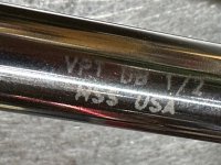
I’m evaluating a new router motor to maybe replace an old PC 7518. The new motor has some nice features like soft start and continuous variable speed and it uses ER 20 collets. The downside is my Eliminator chuck won’t fit.

But the new router seemed to have runout I could detect with my finger tip in the spindle taper.

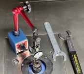
To make a more objective assessment I secured the motor and set up a dial test indicator.

Bottom of taper = .00075”
Middle of taper = .00125”
Near top of taper = .0015”

A fat thousandth of an inch isn’t much but it’s about ten times more than I would expect on the spindle. But I’ve never measured a router spin before but that is more than I want on my drill press. I thought a short router spindle would be tighter than that. Am I expecting too much?

 
That's directly in the taper itself, correct? Seems like quite a bit to me too. Is there any measurable movement in the bearings? What happens if you put a long shank bit in and measure that? Is the entire taper "off center" or is it making a cone?

If you were measuring a shank mounted in an ER20 collet, I wouldn't be surprised. I have run into that with my milling machine at home. QC is apparently not so great in some cases. It's like there is no middle ground with them? Cheap or very expensive
 
The measurements are of the taper itself.

I don’t know if the cone is crooked as well as offset. If I can find my six inch dowel I’ll check but the 2” dowel I used must not be precision, it measured 1.5 to 2.5 thousandths off axis depending on how it was spun in the collet. Checking an Amana bit shaft close to the collet, it was consistently 1.5 thousandths out no matter how it was rotated in the collet. So the collet must be pretty good too, I think.
 
You said "evaluating", does that mean you are not committed yet? Is this unit new? Try another one?
.0015 doesn't sound like much to normal people, but it's quite a bit on something like this, not only is the balance effected, 20K plus RPM is rather serious.
It does funny things to the bit too, changing the chip load. With big bits, the balance is more of an issue, small bits are more annoyed by the chip load per tooth changing.
If you have the choice, I would try another one.
 
Michael, If I have some time this weekend, I'll put an indicator on the 1010, 1400, 2200 and a Milwaukee 5616 Body Grip just for giggles. It'd be interesting.  [smile]

My hunch is that they won't be very different...but that's just a hunch, as they're all precision machines as opposed to some of the others that are on the market.
 
Evaluating as in deciding whether to keep it. I’m confident it can be exchanged or returned and I think an exchange is in the works.

[member=44099]Cheese[/member] hope you get a chance to test some of yours. Now that I have the setup I’ll try to test some of mine.
 
Your numbers are higher than I would have expected.

But what really matters is how the cutting tool runs out.  I would but a straight rod in there and measure the rod runout, at the tip.  Your collets are not perfect either, so put a mark on both the spindle shaft and the collet to see if/how the runout changes with orientation of the collet.

 
Tested two old PC 7518 routers.

The older one, made in Tennessee, .0005”
The “newer” one, made in Mexico, ~.00037”

They have one third or less runout than the new router so it won’t be replacing anything unless it’s replacement is better than a PC.

The PC collets are recessed in the middle so only bear at the top and bottom of the spindle taper. So I measured the runout of the taper high and low and used the worse measurements. Worse at the top in both cases.

I use an Eliminator chuck in the Mexican PC and before taking it off to test the spindle taper measured 1-1/2 thousandths of runout. I recently used it to spin rail and stile bits and it wasn’t too bad. But when putting it back on the spindle I used the testing rig to find it’s best position and got the runout (at the upper end of the Eliminator) down to .00025”, apparently mostly offsetting the errors in both the spindle and the Eliminator to get less runout than either part by itself. These are still just measurements at the chuck and don’t indicate whether there is also yaw in the runout as Steve1 and CRG warned about.

I have a century old Starrett “last word” dial rest indicator, somewhere, but couldn’t find it so I bought this inexpensive SHARS testing rig.

Seems to be a great value since it works pretty well. Increments are .0005 as is typical of dial test indicators so some basic math and reading between the lines is required.

[attachimg=1]


Attachments

  • IMG_1187.jpeg
    IMG_1187.jpeg
    458.2 KB · Views: 452
Michael the true test is the bit in the router or the bit in the drill press. Consider getting a precision dowel to chuck and then measure the runout on that. Here's a selection from McMaster-Carr: I use stainless because I don't have to worry about rust. Tolerances are within 0.0002 of an inch. I think I have a 2 and a 4 inch in 1/2 inch diameter.
https://www.mcmaster.com/products/precision-dowel-pins/dowel-pins~/dowel-pins-7/

Ron
 
rvieceli said:
Michael the true test is the bit in the router or the bit in the drill press. Consider getting a precision dowel to chuck and then measure the runout on that. Here's a selection from McMaster-Carr: I use stainless because I don't have to worry about rust. Tolerances are within 0.0002 of an inch. I think I have a 2 and a 4 inch in 1/2 inch diameter.
https://www.mcmaster.com/products/precision-dowel-pins/dowel-pins~/dowel-pins-7/

Ron

This is exactly what I'm going to do to measure the 4 mentioned routers. I'll install a 1/4" collet in each and insert a 1/4" x 2" long dowel pin. By using the same pin to measure each router you've also eliminated another variable.

I keep a box of these things around in different diameters and use them as a cheap set of pin gages. Unbrako dowel pins are inexpensive and nothing special but they have a ground accuracy within .0002" while lengths are held to within .010". I picked these up from Fastenal.

[attachimg=1]

[attachimg=2]

[attachimg=3]
 

Attachments

  • 13712.jpg
    13712.jpg
    850.9 KB · Views: 422
  • 13713.jpg
    13713.jpg
    795.5 KB · Views: 415
  • Unbrako Dowel Pins.png
    Unbrako Dowel Pins.png
    513.1 KB · Views: 416
Hopefully I’ll find my stash and won’t have to wait…

[member=44099]Cheese[/member]  did you buy or make those transfer screws?
 
Michael Kellough said:
Hopefully I’ll find my stash and won’t have to wait…

[member=44099]Cheese[/member]  did you buy or make those transfer screws?

Made them.
 
Earlier I said, “I recently used it to spin rail and stile bits and it wasn’t too bad.”

This refers to running bits in the Eliminator chuck. I did not have a testing rig then so just went by perceived vibration to tell if the bit was positioned okay. That is, was it worth the trouble to rotate the bit in the collet to reduce vibration. I just stuck my hand under the table and touched the motor housing to feel the vibrations while listening to the sound.

With the Eliminator Chuck rotating the bit and checking vibrations is trivial. Literally a few seconds, only requires a T-handled hex key. (Just turn the wrench until the bit stops sliding then give it another 1/4 turn.) I’m sure I did that before using the bit so “…it wasn’t too bad”.
 
Precision dowels are a nice thing to have around. Chuck a 1/2 inch in the drill press or router and its a great way to set the fence. Need to drill a hole or rout a groove centered 1 inch from the fence, just pop 3/4 inch spacer in between the fence and the pin and with the 1/4 inch from the dowel you have your 1 inch on center.

Ron
 
Tried to measure spindle taper of the OF 2200 but the magnets make it too hard to turn that brushless rotor.

Found the rod I bought years ago for testing the drill press. (But I’d already put the Festool router away)

6” polished stainless .499” diameter. I don’t have access to the McMaster account used to order so don’t know exact specs but it would have been appropriate for that purpose and so should be good for this too.

Chucked it in the new (Chinese) router so the square end projected beyond the bottom of the collet.
Didn’t try to optimize the rotation of the rod in the collet…
Close to the collet the runout was 5/.0005”  (.0025”)
4-1/2” from the top of collet it was 10/.0005”

I could see the end of the rod move back and forth as I turned the spindle.

Anyone recognize this mark?

[attachimg=2]


Attachments

  • IMG_1189.jpeg
    IMG_1189.jpeg
    384.9 KB · Views: 154
  • IMG_1190.jpeg
    IMG_1190.jpeg
    299.8 KB · Views: 393
For comparison, my old Makita budget router runs out .010 TIR at 4.5" from collet (no collet optimization attempted).
 
Steve1 said:
For comparison, my old Makita budget router runs out .010 TIR at 4.5" from collet (no collet optimization attempted).

Yikes!

Since I was only measuring spindle taper I didn’t try to optimize the position of the collet. That would be especially helpful with a long bit.

Looking at the mark on the long rod I found I’m guessing it must be drill rod since it says “HSS”? So it can’t be stainless either? Don’t know if that says anything about how straight it is, or isn’t…
 
High Speed Steel pieces like that are usually called "drill rod" or "tool bit blanks" and are centerless ground. Unless it has been abused in some way, should be dead straight.
I keep a few in 1/4" x 4" in my router bit Systainer. They are handy for all kinds of stuff.
 
Back
Top