Speaker building

Can’t remember the name of the channel at the moment, but there a woodworking guy that got into audio and build a listening room and speakers. He tested mdf vs birch plywood and others (IIRC) and didn’t have much difference between material.

And you can always test the enclosure, measure it, and make adjustment in your component/ crossover design to make it sound optimal for the material you choose.

Now we have active dsp which is even easier to make a speaker sound good because you can change its curves in real time.

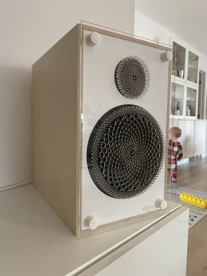
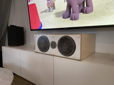
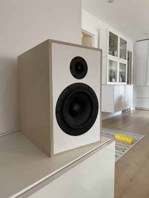
I had the chance to listen to the Solen Mura 5b. The store is a short diatance from ma house. And the guy that designed it is pretty cool. The small-ish speaker that packs a punch. From my ears, at say they’re about 80%-85% as good as my CSS audio criton 1td and 2td. On for home theater uses, it’ll be good enough.

Attached picture of said 1td and 2 td’s
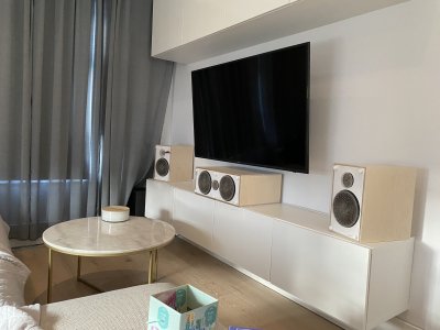
IMG_0740.jpeg
IMG_0755.jpeg
IMG_0727.jpeg
IMG_0760.jpeg
 
@sebr023 I hope you wear hearing protection in the shop. It would be a shame for you and those like you who really appreciate music to have that unnecessarily impaired in the future.

Peter
 
My “top shelf” Radio Shack speakers (which I still have and are pretty good, but not really excellent) we’re purchased circa 1975. They are pretty (real walnut veneer) over 5/8” particleboard.

I don’t know how particleboard compares to MDF acoustically, but cost-wise, not a huge difference. So I guess particleboard was used interchangeably.

Physically, big speakers.

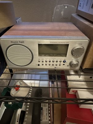
My 25 year old Tivoli Audio radio has remarkably nice sound out of an appropriately 4” speaker and a 5” x 10” x 8” box. Those are appropriate dimensions and I will update when I locate the radio.

That radio is the reason I think acoustic engineering plays a big role in how a speaker sounds. A radio that small should not sound that good.

Addendum:

Still in production, and smaller than I remembered. Updated dimensions: 4.5 x 8.375 x 5.25 in

And apparently they have added blue tooth, which mine does not have.


View attachment 379168
I have the Music Hall model, they do sound great.
 

Attachments

  • IMG_2228.jpeg
    IMG_2228.jpeg
    1.3 MB · Views: 13
On a somewhat related subject, I have seen music practice rooms constructed on TV shows and they are built with sound absorbing materials. That approach is 100% wrong. If anyone is planning on making a music practice room, or needs a separate quiet space, they should start a thread and explain.
 
… I need to reconsider learning Fusion …

Earlier this year Peter Millard tried a bunch of modeling tools for his new 3D printer.

After all the trials, Peter learned that Shapr3D was the best fit for the way his mind works.

A few other woodworkers have made that same decision.

If Fusion360 gets frustrating, you might wanna give Shapr3D a try.
Thanks for that...I'm an Autocad guy but I refuse to purchase the software for a $5000 stipend when I design stuff maybe once a month, and all the stuff I design is for personal use. Nothing gets sold, nothing gets released to other manufacturers...it's a very closed loop deal.
 
Thanks for that...I'm an Autocad guy but I refuse to purchase the software for a $5000 stipend when I design stuff maybe once a month, and all the stuff I design is for personal use. Nothing gets sold, nothing gets released to other manufacturers...it's a very closed loop deal.
I believe shapr3d is free, or had a free tier
 
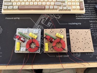
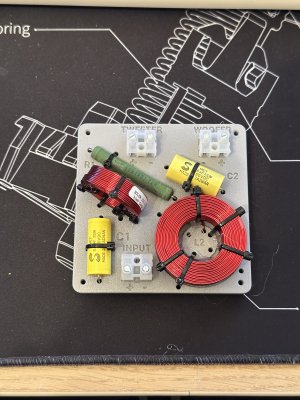
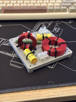
Today I worked a bit on the crossover, mainly the board.

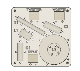
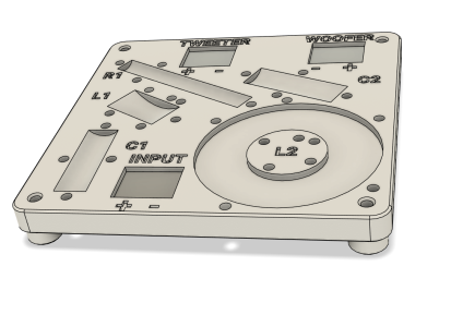
The kit comes with mdf-like board. I modeled and 3d printed a board.
Nobody will ever see this once it’s in the speaker enclosure, but I’ll know

IMG_7943.jpeg

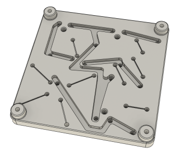
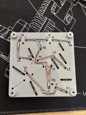
I created some relief in the board with the shape of each component, and all the channel for the wire and solder on theback.
Capture d’écran 2025-11-10 191331.pngCapture d’écran 2025-11-10 205800.pngCapture d’écran 2025-11-10 205831.png
 
Last edited:
If Fusion360 gets frustrating, you might wanna give Shapr3D a try.
There are a number of really good YouTube channels with Fusion tutorials.

For 3D printing, it might be overkill, but for CNC machining, nothing else that's free generates as good toolpaths, especially for 3D objects (not just cutting out plywood with a ¼" bit or doing V-Carves, for which there is speciality software just for those).
 
I really like the 3D printed crossover board. Great idea and nice execution. (y) I'd love to see the back of it once you populate the board and make all the solder connections.

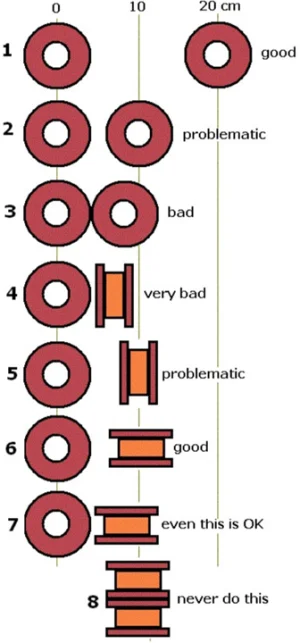
What determines if the inductor coil is mounted flat or is mounted vertically?
I could be wrong, but I guess it’s the place on the board.

Edit: I was wrong, here’s the answer I found :
Coils have a magnetic field. Neighbouring coils will be affected by this magnetic field. To minimize that they should be mounted at 90 deg. to each other.
 
Thanks for that...now that makes sense. :cool:

So, for a 4-way crossover you'd probably mount that on 2 separate boards and space them at some distance from each other inside the enclosure.

So answering my own question, I found this example of proper inductor orientation.
 

Attachments

  • Inductor orientation.webp
    Inductor orientation.webp
    137.7 KB · Views: 11
Last edited:
Thanks for that...now that makes sense. :cool:

So, for a 4-way crossover you'd probably mount that on 2 separate boards and space them at some distance from each other inside the enclosure.

So answering my own question, I found this example of proper inductor orientation.
I think it depends on the power in watt of said speaker. I read that 5 watt speaker you wouldnt here the difference, but 100w speaker its important.
 
Thanks for the rear view of the populated board with the solder connections... 🙏 I find it interesting that even you need to label the components on the rear of the board. :) I successfully identified the individual component holes but it was certainly a brain twister. at the time. :) Those 3D printed boards are really the way to go, they're so much better than the FR-4 variety.
 
Really nice job on the circuit boards, between CNC, laser engraving, and 3D printing it's just sensational the sort of stuff you can tackle and create now, that would have been unthinkable not that many years back.
 
Thanks for the rear view of the populated board with the solder connections... 🙏 I find it interesting that even you need to label the components on the rear of the board. :) I successfully identified the individual component holes but it was certainly a brain twister. at the time. :) Those 3D printed boards are really the way to go, they're so much better than the FR-4 variety.
Yeah, I mean i was pretty sure, but i was looking at the diagram of where each component need to be and solder too and I second guessed my self. and writing what every thing comes from and goes too is very helpfull.

Really nice job on the circuit boards, between CNC, laser engraving, and 3D printing it's just sensational the sort of stuff you can tackle and create now, that would have been unthinkable not that many years back.
Thanks! yeah its incredible to have this level of home manufacturing now! Really elevate the build levels of details and finish
 
Back
Top