Underbench cabinet

Nice work Derek!

Curious where you have one divider above the other why you would not just use mortises.  The drawers are small and I'd think you are most interested in sticking of a drawer from the weight of the one above.

Appreciate the process photos.

Neil
 
Thanks for the kind words, Neil.

The reason to use sliding dovetails on the outer dividers is to create unity and strength, as you realize. It is not critical for the inner dividers to be dovetailed. I do so for uniformity ... and pride of workmanship. Every time I stand at the bench and reach for a tool, I want to feel that I did not wimp out when building the cabinet. Pride can be a terrible thing. Here, it made me go the extra length and mitre the ends of the case. It made me aim for frames for blades rather than the easier solid option. And there is more to come ..  [cool]

Regards from Perth

Derek
 
Progress report ...

I am pleased to get to this stage, with everything still square ....

... 24 sliding dovetails done.

Only a dry fit - now to glue it together ..

Current1.jpg


Current2.jpg


Regards from Perth

Derek
 
It seems so straight forward: build the case, insert drawer frames and dividers, and build the drawers.

Each step actually requires planning ahead. The devil lies is in the details. These are some of the details we take for granted ...

Step one is to plane the fronts of the rails and dividers, and fill in any chips with tinted epoxy.

Even gluing up requires a strategy when the case includes blind sliding dovetails: glue these first.

The benefit of liquid hide glue is extended open time and repairability. I hope that I do not have to make any repairs, but I could do with the open time as it is 40° Celsius today (that's 104° Fahrenheit). I like a small spatula for placing glue where it needs to go.

Glue1.jpg


Glue the first set of blind sliding dovetails, and then the other set ...

glue2.jpg


Finally glue in the other dividers ...

Glue3.jpg


Lastly, add the drawer guides. These are just glued in. The spring clamps centre them.

Glue4.jpg


Once all this is dry, we start to prepare the drawer cases. Each one of these needs to be square at the sides and parallel all the way through.

The planes I find helpful are these: a rebate jack, a rebate block plane, and a low shoulder plane ...

Tune1.jpg


For each drawer case there is a drawer-sized insert, generally of MDF or ply. A couple of cross lines aids in determining whether the drawer will be square to the sides.

The "drawer" here does not enter more than an inch or so ...

Tune2.jpg


A straight edge along the side reveals that there is a bow ...

Tune3.jpg


The block plane takes this down ..

Tune4.jpg


... tested with the insert. Looking better ...

Tune5.jpg


A little more planing ... and the insert moves tightly, but smoothly all the way back-and-forth ...

Tune6.jpg


Every drawer case is dealt with this way ...

Square edge ..

Tune7.jpg


Planing ..

Tune8.jpg


Square and insert ...

Tune9.jpg


Tune10.jpg


Square and parallel and square ...

Tune11.jpg


Every drawer case is tuned this way.

Now we are almost ready to make drawers :)

Regards from Perth

Derek
 
This chapter follows on from "Before the Drawers", in which I ended stating, "Now we are one step away from making drawers". And now this chapter is that penultimate step ...

I need to explain some of the (as I feel) pedantic details I have been outlining. Firstly, I write this for those who are starting out and those who are seeking ways to increase their accuracy. The steps may not be new to some, but we all like to be reassured that others also find them necessary.

Secondly, I am going to introduce a fixture I built that increases not only accuracy, but speeds up a section of the work. This is the first time I have had a chance to try it in a furniture build.

So what do we need to do today? Well, we need to cut the drawer parts (minus the drawer bottoms) to build the drawers  :)

I spent time selecting the wood for the drawer sides and drawer front-and-back. The sides were jointed and thicknessed by machine, and then stickered for a few days ...

PD1.jpg


The drawer sides are to be 7mm thick, which is more typical of the drawers I build for furniture than a tool cabinet, however the drawers will each house a tray - some sliding and some cantilevered - which effectively doubles the thickness. My aim is to be sturdy but also save space (since the tool cabinet is on the small side, as it must fit under the work bench).

The drawer front is 18mm. The drawer back is 12mm.

For reference, mentioned at the start of the build, the dimensions are:

Dimensions: 660mm x 400mm x 400mm (26" x 15 3/4" x 15 3/4").

Small drawers: 205mm x 70mm (8" x 2 3/4")

Large drawers: 305mm x 95" (12" x 3 3/4")

UnderbenchCabinet1_html_1bba671c.jpg


Time was taken to select the wood for the drawer fronts.

The issue here is that I was not after figure, but constancy of grain and colour (although a little tinting could be done with a latter). Lots of combinations tried ...

PD2.jpg


Now to the fixture. Actually, there are two fixtures.

I recently posted a design for a Parallel Guide for a slider table saw (mine is a Hammer K3). This article is here:http://www.inthewoodshop.com/Powered Tools and Machinery/ParallelGuideForK3Slider.html

ParallelGuideForK3Slider_html_1fdf2a4a.jpg


The other design I posted was for a Micro Adjust for the crosscut fence:http://www.inthewoodshop.com/Powered Tools and Machinery/CrosscutFenceMicroAdjust.html

CrosscutFenceMicroAdjust_html_m2c7dfdb0.jpg


These new addictions made sizing the drawer fronts and backs much easier, and quicker.

Generally, I would rip a board to rough size for the drawer front (and back, since they must be an exact copy of each other), and then fine tune it with a shooting board and hand planes. Well, these tools continue to be used, but I can get pretty close to final dimensions on the slider alone. The parallel guide replaces a rip fence, and it is both safer to use as well as leaving a cleaner finish than off a table saw rip fence.

Here is the crosscut fence cutting the width of a drawer front ...

PD3.jpg


With the use of the Micro Adjuster, it is possible to sneak up on the width and "shoot" it with the table saw, to such fine tolerances only previously capable on a shooting board ...

PD4.jpg


Minute adjustments can be made to the cut, with the aim of a tight fit side-to-side.

Once the drawer front is done, it is a simple matter to cut the drawer back using the same setting ..

PD5.jpg


Now is the time to rip the height if the drawers fronts and backs (although the drawer backs will receive further shaping at the time of drawer making). This is a test cut. It needs to be repeated for each line of drawers, and checked for each drawer ..

PD6.jpg


As mentioned earlier, the aim is a tight fit throughout ...

PD7.jpg


Once all are done, comes the time to tune each. The main tool use for the upper edge is a shooting board ...

PD8.jpg


Ensure one side fits smoothly ...

PD9.jpg


... and the other ...

PD10.jpg


The ends need some tuning as well. This is to remove a smidgeon here-and-there, to ease a section where the sides may be touching or even jamming. It may require a shaving, or just dust. The tool of choice here is a block plane.

PD11.jpg


My aim here is a smooth fit - not loose but not tight: at the end, after the dovetailing is done and the sides are glued together, I want the drawer to dry in the drawer case. Therefore, it needs to be able to fit. I expect to do a little tuning still, but the aim now is to prepare for this fit.

The drawer back needs to be tuned up identically to the drawer front - the smidgeon "here-and-there" included. So, clamp the parts together ...

PD12.jpg


I prefer a sharp, wide chisel to pare away the excess waste from the drawer back ...

PD13.jpg


This leaves the fronts and backs ready, so ...

PD14.jpg


The last task is to saw the drawer sides. This is made a quick job by the parallel guide, and using the drawer fronts as a template.

Once side of a drawer front will dimension the height of that drawer side ...

PD15.jpg


Rip it ...

PD16.jpg


Test the fit in the drawer case. Any tight spots can be removed with a shooting board or block plane. This is what we are after ...

PD17.jpg


... and eventually ...

PD18.jpg


Now we are ready to start dovetailing. :)

Regards from Perth

Derek

 
Beautifully detailed and helpful Derek. You are an artist.

Sent from my iPhone using Tapatalk
 
The detail with which you describe the journey to the finished product is much appreciated. I always learn a lot from reading your posts, precisely because of those details and your habit of describing the reasoning behind the choices made! To me there's no way that could be interpreted as pedantic! Not only that, but it is very entertaining to read these post too.  [thumbs up]
 
Dovetailing for Blood

Bill and I have been discussing drawer-making. We have different approaches since our target audience is a different group. Bill is better aligned with production work, aiming to build a drawer as quickly as possible. He is less concerned with aesthetics (although his work always looks exceptionally good) and more focussed on finding shortcuts to increase speedier construction. My work is aimed at being the best I can, with a focus on traditional construction completed to as near perfection as I can muster (which sounds grander in words than in practice!).

I argue that my drawer-making is quite speedy. The speed comes from minimising unnecessary tasks by planning ahead. This is not immediately apparent in that I use techniques that appear to add extra work. In actual effect, they reduce errors and thereby reduce the time required to tune or repair joinery. My aim is to get it as right as possible - immediately. One example if this is that I do not check whether the drawer is square after glue up ... because the drawer will dry in the drawer case, and so fitting the drawer case is what is important.

Now the issue about fitting the drawer case is that this is only possible if the dovetailing is a flush fit, and ready to go into the drawer case. It is expected to be a tightish fit, which will need to receive just a small amount of final tuning. The level of expertise involved here is not really that high; it is more about the approach. I believe anyone can do the same, and this is the motivation to write this chapter. I am sure that Bill will likely do the same ... I look forward to learning from his approach, adding technique to my own.

The discussion started when Bill questioned why I had cut all the drawer parts (sans the drawer bottom) for this cabinet ...

PD18.jpg


Bill makes one drawer at a time. He does this as he is concerned the wood will move .. warp or twist .. if it is allowed to rest. My argument is that speed comes from massed repetition: returning to saw all the parts separately is slow. I do not fear the drawer sides moving as I use quarter sawn timber for drawer sides, which is very stable. The wood here is Tasmanian Oak (which is actually an Australian Eucalyptus).

The drawer-making process is divided into three stages: first comes the (half-blind) dovetailing of the sides to the front. The groove or slips for the drawer bottom is added later.

Secondly, the drawer back is (through) dovetailed to the sides. This relies on the height of the groove, and the reason it is completed later and not up front.

Thirdly, the drawer bottom is made and inserted.

What I wish to demonstrate here is the first stage: dovetailing the front to the sides.

Here are the parts. The Tassie Oak sides are 1/4” (6.35mm) thick and the Jarrah front is 3/4” (18mm).

D1.jpg


The inside face of the drawer sides is planed to remove any machine marks ...

D2.jpg


We will cut Tails First, so mark the tail board ...

D3.jpg


To speed marking of the tails, a template (or story stick) is made. This will set out the tails for the top two rows, six drawers in all.

D4.jpg


The tails are sawn. Note that there is a line of blue tape to help my aging eyes know when to stop cutting!

D5.jpg


An important step is to undercut the baselines. This will increase accuracy when paring ...

D6.jpg


Fretsaw the waste as close to the baseline as possible. I generally leave about 1mm ...

D7.jpg


Saw away the half sockets at each side, as usual. But now possible to set the chisel in the chisel wall and use a single down stroke to sever all the waste in the internal sockets, leaving the tail board done.

Mark the web on the drawer front. For 18-19mm drawer fronts, I keep make this 5mm wide.

D9.jpg


Once again, to aid visibility, blue tape is applied to underline the baseline ...

D10.jpg


... and the pins. Here it extends to the web line ...

D11.jpg


This next bit is extremely important, and can make-or-break the final result. The tails are transferred to the pin board. A single bevel knife is preferred. This will hug the wall of the socket, and slice the tape in a single stroke.

Secondly, the tail board is held firmly by a clamp, and is positioned squarely using a combination square. The square is placed along the reference edge, which is the lower edge of the drawer side. This will switch when the other side is marked out. The importance of this technique cannot be overstated: a squared joint is a prerequisite for a perfect fit. Anything that is not square will require planing, and a lot more tuning.

D12.jpg


Below is the result of sawing to the line (is the sawing is more accurate than the dropped lines :)  In practice, the dropped lines are unnecessary if you have a decent sense of plumb) ....

D13.jpg


Another time saver comes in the form of deepening the kerfs. This is my version of Tage Frid’s scraper method, a “kerfing chisel”.

D15.jpg


With the kerfs deepened, remove all the blue tape, and deepen the base lines ...

D16.jpg


Undercut the baselines to create a chisel wall for each socket ...

D17.jpg


Chisel in the chisel wall and three moderately firm hammer blows. The chisel wall prevents the chisel moving backwards and over the baseline. This means that chiseling can start at the baseline, itself, and reduces later extra paring ...

D18.jpg


Split out the waste ...

D19.jpg


With hard Jarrah and a decent Japanese chisel, it takes me three rows to get within 3mm (1/8”) of the web line. I stop at this point ...

D20.jpg


This is repeated at the other end of the board ...

D21.jpg


Back to the Moxon Vise: the sockets are cleared by paring the remainder in 1mm slices ..

D22.jpg


Cleaning out the socket was facilitated by earlier extending the kerfs, and now with a corner chisel ...

D23.jpg


It is all about “release cuts”, as David Charlesworth has written in his articles over the years. Create a release cut, and waste will fall away without a fight. The deepened kerfs mean that there is no further paring needed at the sides of the sockets. Clearing the waste is a matter of splitting it out. The chopping is a release cut here.

Finally! The dovetailed sides are tapped into the sockets of the drawer front. The goal here is that they fit “off the saw”, and no further work is needed? Note that the small section here does not only protect the surface, but it ensures it is driven flush ...

D24.jpg


How did we do? Here is one side ...

D25.jpg


And here is the other side with the “drawer” inserted into the drawer case ...

D27.jpg


The drawer can be pushed flush into the drawer case, which was the target at the start ...

D28.jpg


Regards from Perth

Derek

 
Beautiful work Derek.

I've only recently found your website after starting hand tool work. What a fantastic resource you have created!
 
Thanks Joel. I hope you enjoy reading the articles, and finding helpful answers.

Regards from Perth

Derek
 
I recently wrote that I aim to build as best as I can. Sometimes it does not go well at all :(

I make two repairs today. Usually, the mistakes I make are as I get spatially challenged, and cut the wrong side of the board. The first one here was being a little over-enthusiastic with a block plane when trimming a drawer front (a few days ago). The problem is difficult to detect from a distance ...

R1.jpg


... but close up .... !

R2.jpg


darn. The drawer front is part of a set of three. It cannot simply be replaced. One also cannot glue a filler to the side of the board.

But one can add a filler to the drawer divider ...

R3.jpg


Here it is glued proud ...

R4.jpg


When trimmed flush, it is nearly invisible. With a coat of finish, it will be ...

R5.jpg


R8.jpg


The second fix was this ... after all the mention I made about the importance of a combination square to ensure the side was square to the drawer front ... well, one got away from me. When I placed the three sides on a flat surface, the far end of one side was about 3mm high.

This was the fix. Can you spot the repair?

R6.jpg


Eagle eyes will note that there is a light line. This is where a triangular fillet was glued in, and planed flush (The corresponding top side needed to be planed down to fit inside the drawer case).

R7.jpg


Regards from Perth

Derek
 
Great tips.  The challenge is not making mistakes, but effectively recovering from them!

 
Perhaps I need to explain the title, "Dovetailing for Blood". In part, the description comes from a book, "Backgammon for Blood", by Peter Becker I read about 4 decades ago. It's about taking the game to the most competitive level. This series of articles is not a how-to about dovetailing; it is about the strategies I use when building drawers. I offer them for discussion and your interest.

D2-1.jpg


This is the drawer in question.

In the previous article, the focus was on strategies for connecting the drawer front and drawer sides via half-blind dovetails. The aim there - and continued here - is to complete the dovetailing in such as way that the drawer may be glued up, and dry inside the drawer case. The advantage of drying inside the drawer case is that a good fit is assured.

Today the drawer back needs to be attached with through dovetails.

D2-2.jpg


For interest, here are the chisels I used: Kiyohisa slicks and Koyamaichi dovetail.

D2-3.jpg


Noticeable in the drawer above is that there are no grooves for the drawer bottom. These will now be added using a plough plane and a sticking board to hold the work...

D2-4.jpg


D2-5.jpg


The drawer sides are around 7mm at this stage, with the expectation that they will end up at 6mm. The inside and outside faces have been planed. The groove is 3mm deep ...

D2-6.jpg


The groove in the 18mm thick drawer front is 6mm deep ...

D2-7.jpg


The drawer back receives a shallow groove ...

D2-8.jpg


Reason?

The drawers are designed for a tool cabinet. Unlike drawers for the home, where the backs are lowered, these drawers will have a full rear, in height, ending at the drawer bottom. We start with drawer backs exactly the same dimensions as the drawer front. The lower section needs to be removed. The top of the groove marks this position.

The waste is removed on the table saw, a smidgeon grace ...

D2-9.jpg


... and the machine marks then planed away.

It needs to be stated that drawers are not the same as boxes. While they may both be dovetailed, the drawer width is determined by width of the drawer case. It cannot be larger or be smaller. The drawer front and back are made as a pair, and their dimensions are not permitted to be altered.

With boxes, one can leave dovetails proud, and then level them to the sides. Or one may level the sides to the dovetails. You cannot do this with drawers, especially if the game plan is to aim for the glued up drawer drying in the drawer case. Consequently, the dovetails must end up flush with the surface ....

D2-10.jpg


We move over to dovetailing the rear:

The first step, with 6 drawers of the same height and width, is to make a template for the spacing of the dovetails.

D2-10A.jpg


While the template stretches across the board, the area of importance is above the drawer bottom.

Mark out the tails, as usual, but then flip the board so that you are sawing from the inside of the drawer ...

D2-11.jpg


Again, this is not a box. The inside of a drawer is seen, and it is important to keep the baseline as clean as possible, that is, no over-sawing.

Similarly, when removing the waste with a chisel, start with the outside face of the drawer, and finish with the inside. That way there is less danger of inadvertently chiseling over the baseline.

D2-12.jpg


Now ... the interesting part comes with transferring tails to pins. This can make-or-break the drawer.

D2-13.jpg


Here we see the tail and pin boards aligned. But are they?

D2-14.jpg


A square shows that the side is out at least 1-2mm at 300mm (12").

D2-15.jpg


Left like this, the drawer will not sit flat. It will act as if it has a twist. Significant efforts will need to be made to align the drawer in the case. It becomes essential that the side is aligned accurately. This can be a little fiddly, but a long square helps considerably ...

D2-16.jpg


At some point, someone will mention the side-alignment fixture designed by David Barron. This is a wonderful concept, however it excels at making boxes and not drawers. Look here ...

The tail and pin boards are not aligned at the square ends (which would enable David's fixture to be used). They are aligned on the reference side, which is the lower edge of the drawer sides. You are aligning from the left side of these boards ...

D2-19.jpg


Having transferred and sawn the tails, the bulk of the waste is removed with a fretsaw (as detailed before). Here is a reminder - first chop out the waste from the outside face, half way down ...

D2-22A.jpg


... and then complete from the show-inside face.

My preference is to angle the chisel slightly away and create a "tent" ...

D2-22B.jpg


This is then removed with a slicing paring action, again form each side to the centre ...

D2-22c.jpg


Use a narrow chisel to pare the ends: having first sawn these away, the remnants for paring lie above the chisel walls (again discussed in a previous article) ..

D2-21.jpg


This is what we are after: flat ...

D2-23.jpg


Dry fit ...

D2-24.jpg


The drawer must fit the drawer case ...

D2-25.jpg


D2-26.jpg


D2-27.jpg


It does, but we are not finished. More in a while ..

Regards from Perth

Derek
 
The aim is to glue up the assembled drawer and let it dry in the drawer case.

This drawer fits ...

D2-25.jpg


... however it is a tight squeeze and I know that there are issues which need to be corrected before glue is applied. It is the same for every drawer.

Each drawer needs to go through an assessment, trouble-shooting for issues, until the drawer moves smoothly.

I need to point out at this stage that, although drawers are made in batches (a row), each drawer is fitted, tuned, and glued up before assembling the next drawer. At this stage, six (of ten) drawers have been completed to this stage. There is one further stage after this chapter.

So we pull the drawer out of the case. It comes out with effort. The sides twist slightly - I can feel one side is moving more freely than the other. Something is causing it to hang up.

Examining the half-blind dovetails, the first item of note is that there is a slightly raised pin ...

D3-1.jpg


Since the drawer is a dry fit, it is a simple matter to knock it apart to make any fixes.

The pin is planed flat.

I note that the one drawer side sits a little proud at the underside, about 1mm ... maybe not even that much ..

D3-2.jpg


This is also planed down.

The drawer back is presented to the case opening ...

D3-3.jpg


It is a tight fit now. It will be a tighter fit later if there is moisture in the air. The drawer back is removed and the height planed down by about 1mm. Re-assembled,
the sides now are higher ...

D3-4.jpg


The sides are planed to the side height ...

D3-5.jpg


I can still feel a little more stickiness on one side. Are the sides flat, or has there a cup developed to create a high spot?

Yes. Slight but it is there ...

D3-6.jpg


Plane this flat. Just a few thin shavings ...

D3-7.jpg


Now the drawer is moving well - it feels taut, but free.

The case is waxed, not so much at this stage to promote ease of movement, but to prevent any glue adhering to the sides ..

D3-8.jpg


Now we are ready to glue the drawer parts. Here are the items involved ...

D3-9.jpg


I am using Titebond Liquid Hide Glue. I like that it has a longer open time, that it is reversible, repairable, and cleans up with water. There is a spatula for application, a fishtail chisel handy if a corner needs to be cleaned, a small mallet, and a wet rag.

The hide glue is decanted into a small bottle ...

D3-10.jpg


This small bottle is a game changer! I was watching Rob Cosman and noted that he used small bottles as well. I found a bunch on eBay. What they do is let you deposit glue in exactly the spot you want to do, and then the spatula lets you spread it around.

I only glue one side of the joint, but there is enough for both sides ...

D3-11.jpg


D3-12.jpg


It is important that the sides are seated flush ...

D3-13.jpg


The drawer looks good ...

D3-14.jpg


... and, importantly, slides into the case smoothly and firmly.

Regards from Perth

Derek
 
Drawer Bottom and Slips

One of the least pleasurable areas of drawer making is fitting drawer bottoms. Why? Because there always seems more to do than anticipated - there are more panels to machine to thickness and area, and this feels like it is endless. Mindless.

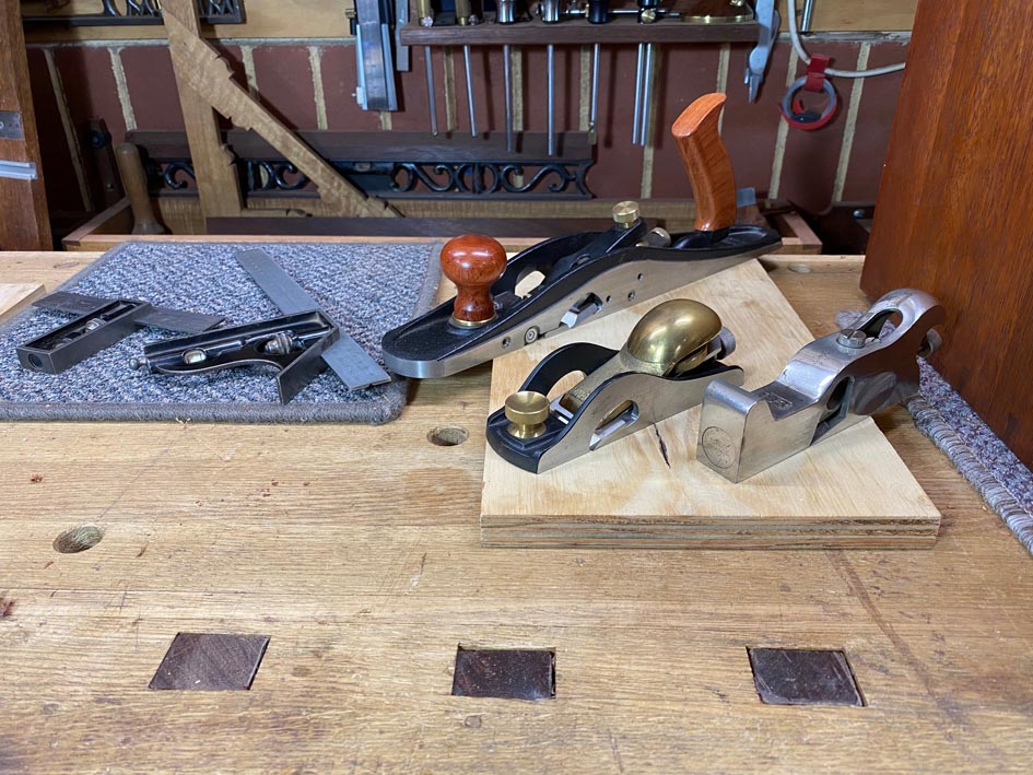
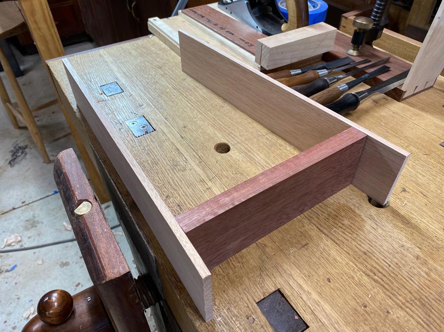
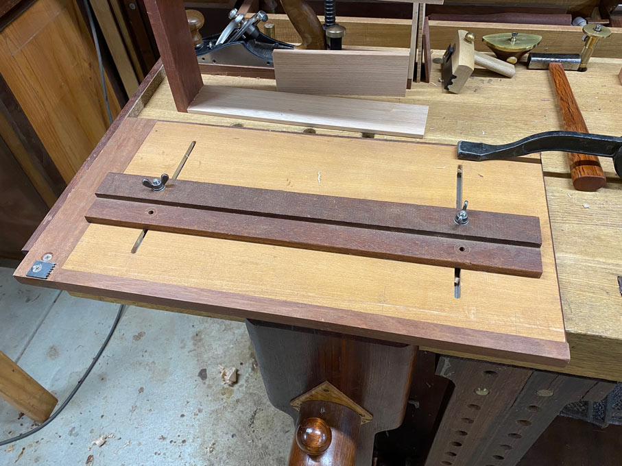
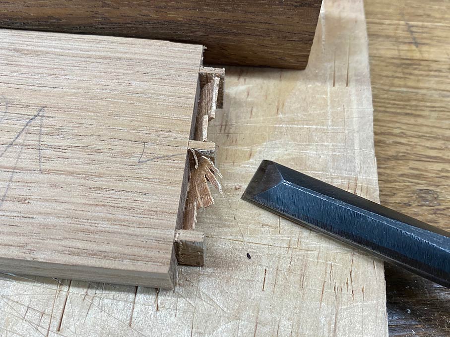
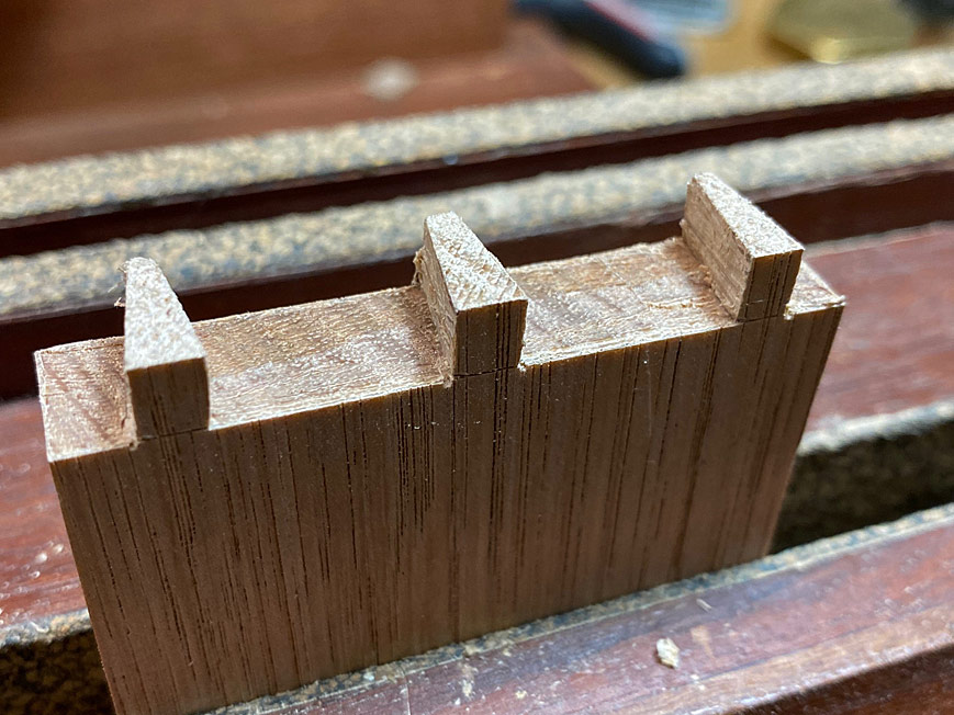
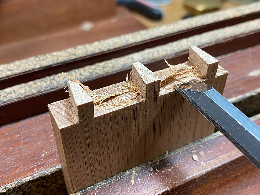
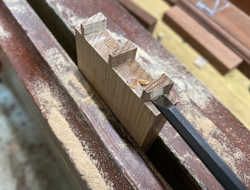
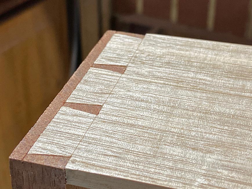
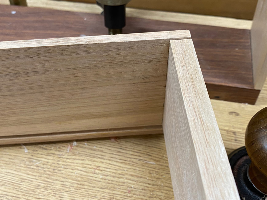
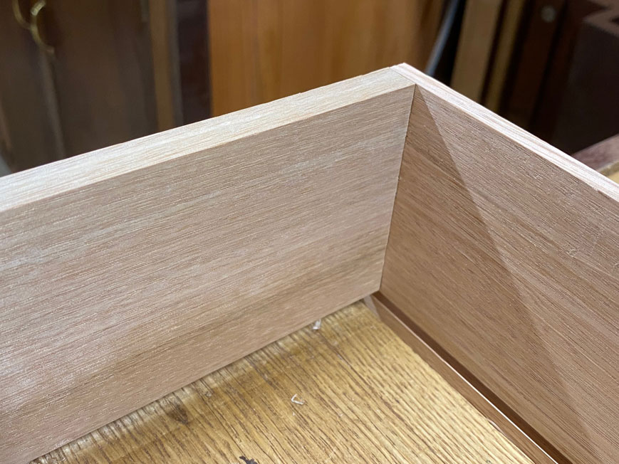
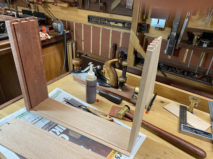
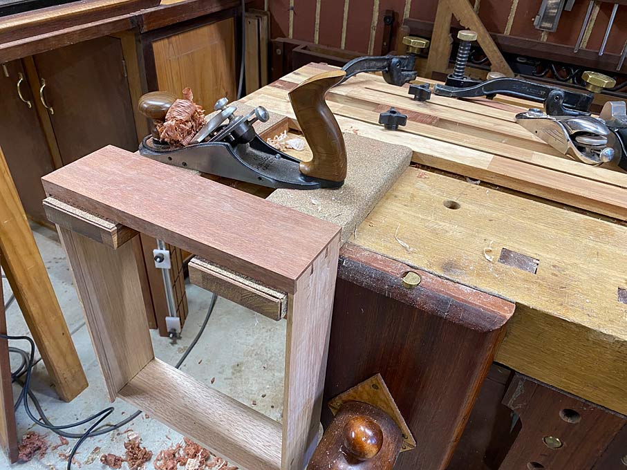
Before starting on the bottoms, the drawer fronts are planed, chipped dovetails repaired, and fine-tuning of the bottom-less drawer is completed ...

Bottoms20.jpg


Link to the fixture here: http://www.inthewoodshop.com/ShopMadeTools/DrawerPlaningFixture.html

One of the rules I set for myself at the start of this project was that, being a just for the workshop, I would use as much scrap or cheap wood as I could scrounge up. The Jarrah drawer fronts are the exception. The case is Merbau stained to match the Jarrah drawer fronts.

Over various projects, I save bits which I think may be used ... don't we all :)  
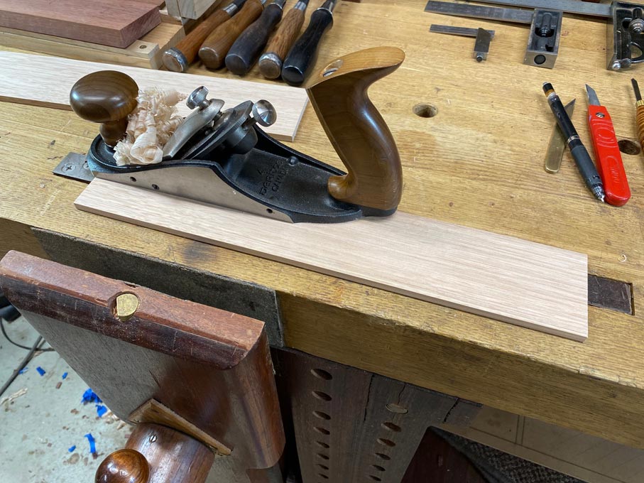
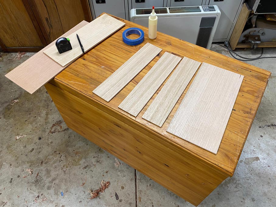
For now, offcuts of Tasmanian Oak, which make great drawer sides and drawer bottoms.

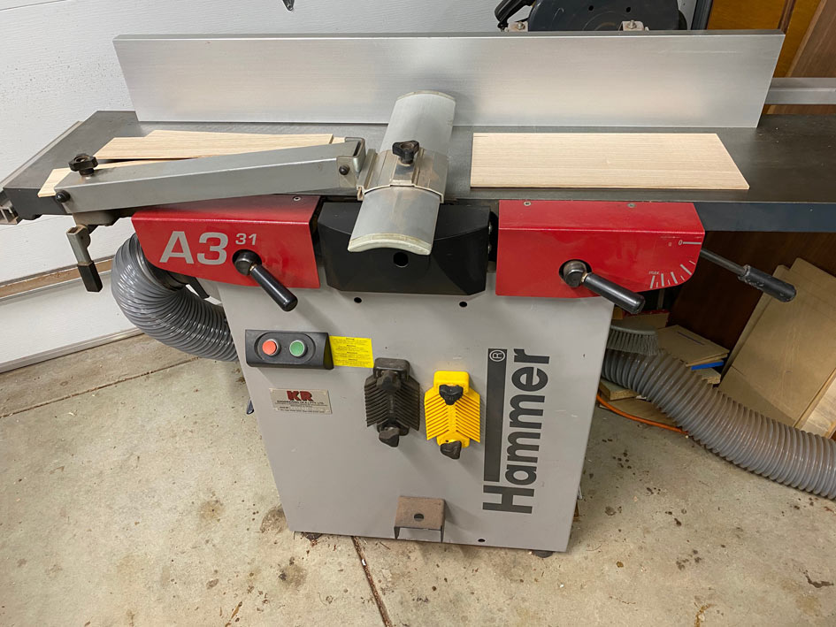
Modern machines, such as jointers and thicknesser/planers, enable the redesign of cabinet parts. In this case, drawer bottoms. One can use the minimum thickness, saving weight and wood.

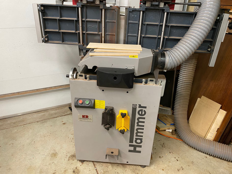
I am very fortunate to own a Hammer A3-31, which turns the scrap into usable boards ...

Bottoms1.jpg


Bottoms2.jpg


Bottoms3.jpg


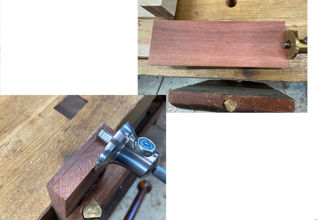
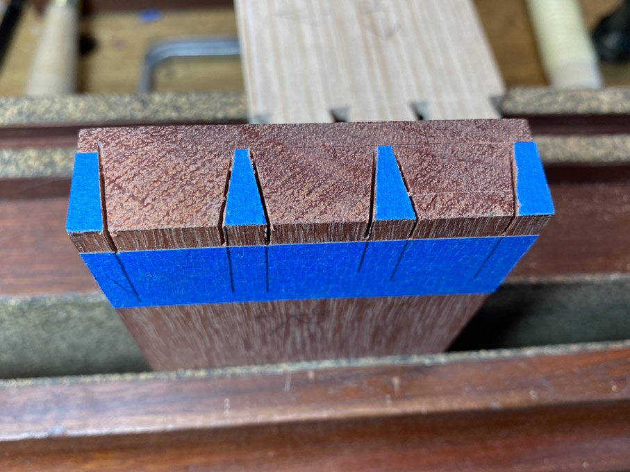
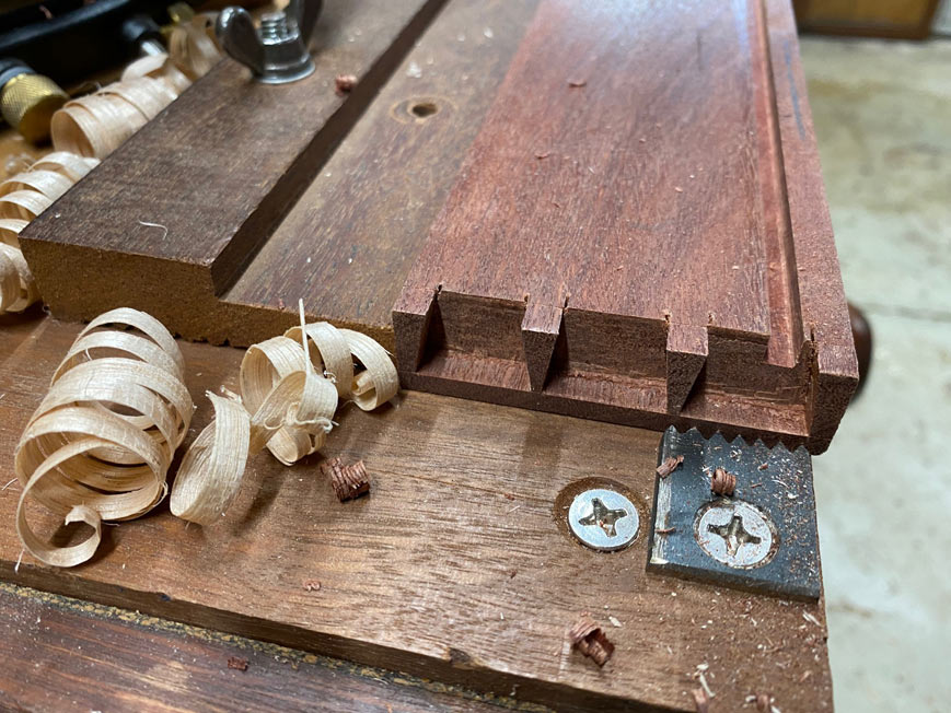
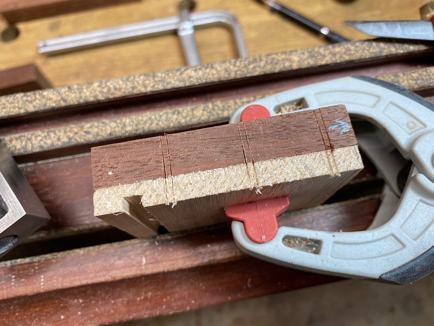
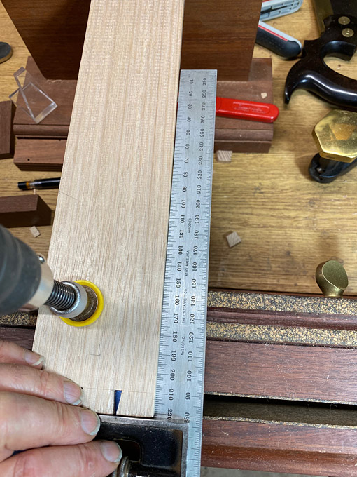
These boards ended up a smidgeon over 5mm thick. The grooves in the drawer sides are 5mm wide and 3mm deep. The drawer sides are 6-7mm thick.

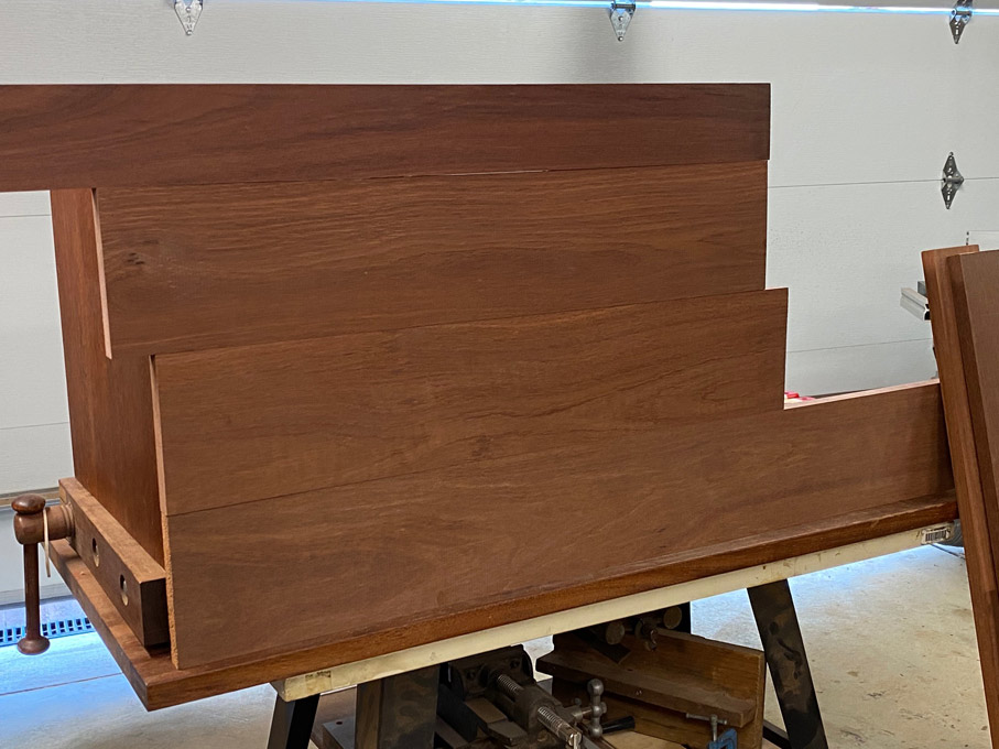
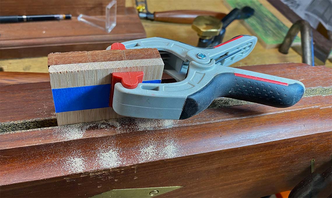
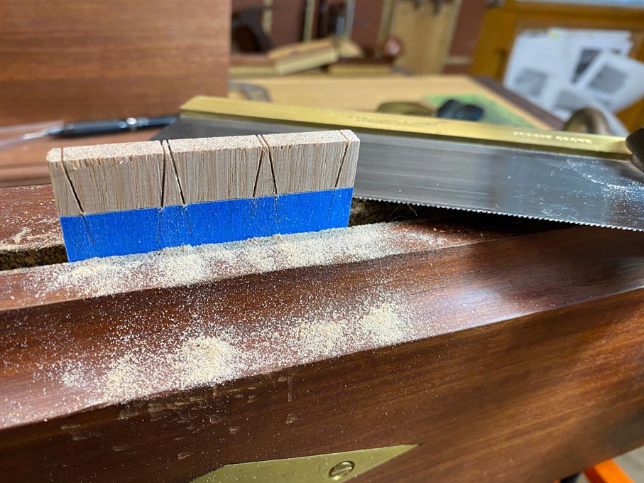
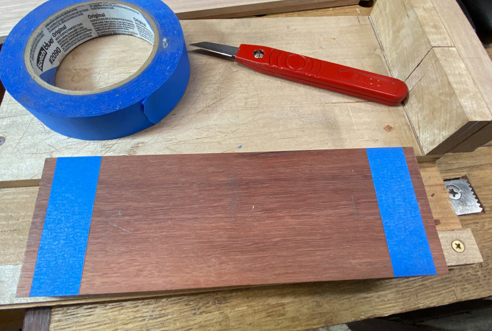
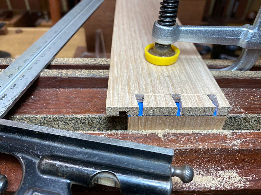
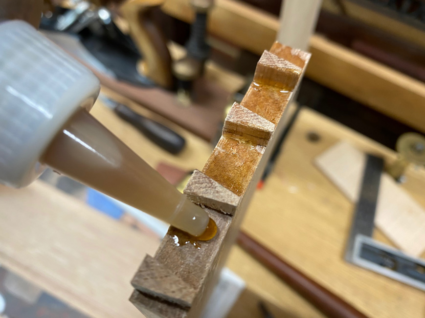
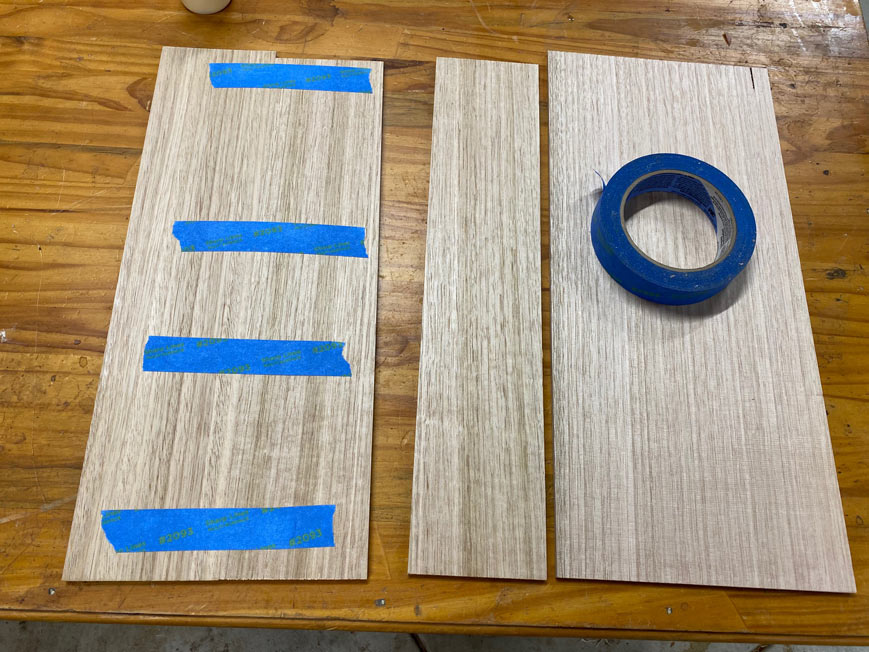
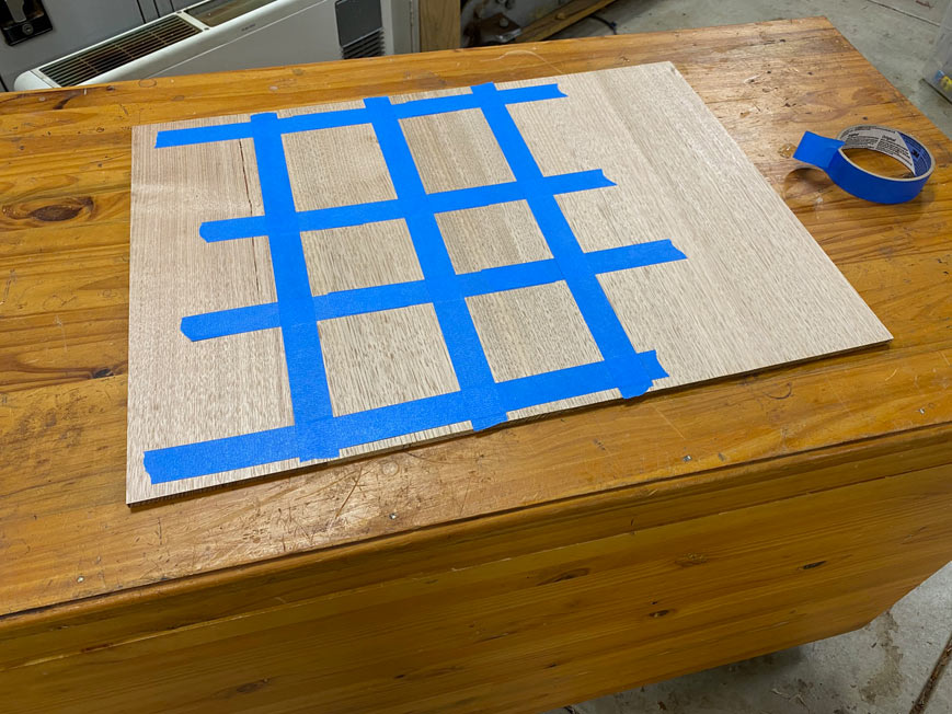
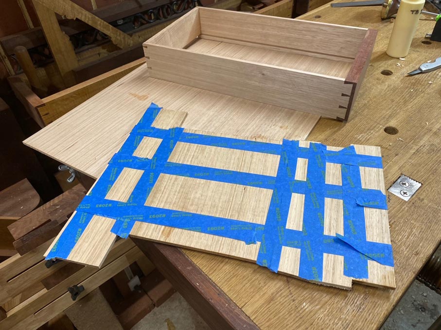
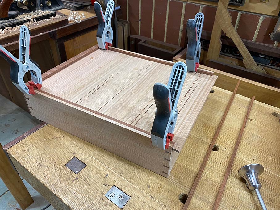
Joining such thin boards is quite easy - no clamps used. Just blue tape :)

Butt two boards, and stretch the tape across the join. The blue tape has some flex to it, and the stretch contracts and pulls the joint tight ...

Bottoms4.jpg


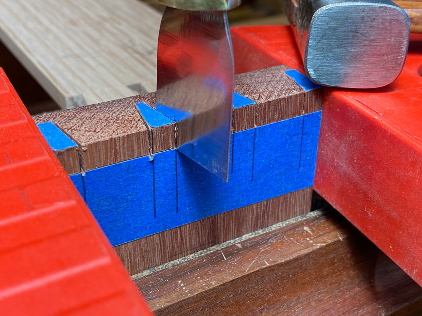
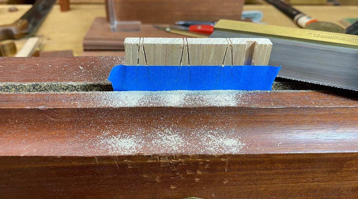
Do this with all the joins, and then lay a strip down the seam (which is to prevent glue squeezing out ...

Bottoms5.jpg


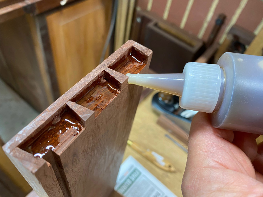
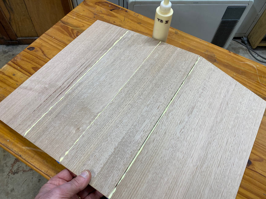
Flip the boards and insert glue into the seam. Wiggle the boards open-and-closed to spread it evenly.

Bottoms6.jpg


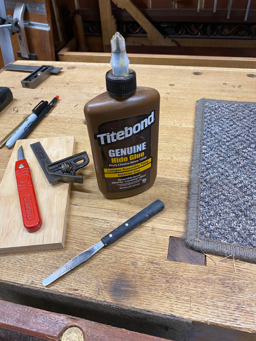
Lay flat and wipe away the glue (Titebond II) squeeze out with a wet rag. Freshen this for each join.

Bottoms7.jpg


Yes, I know many warn against this practice, but I have not experienced any problem with finishes. Once clean, tape the side to hold the joins tightly together ...

Bottoms8.jpg


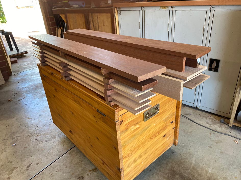
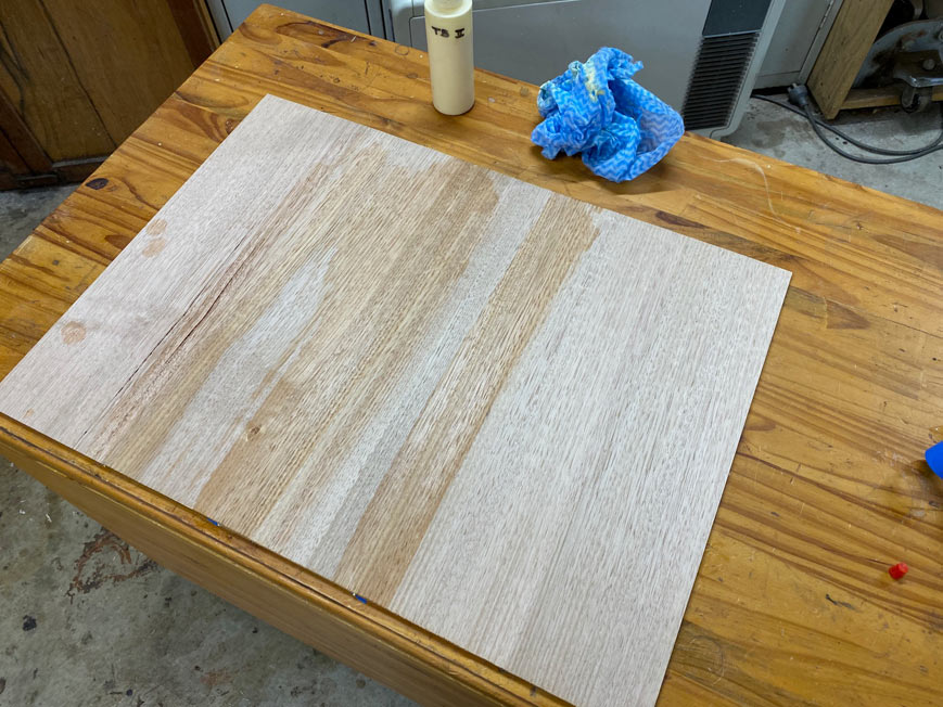
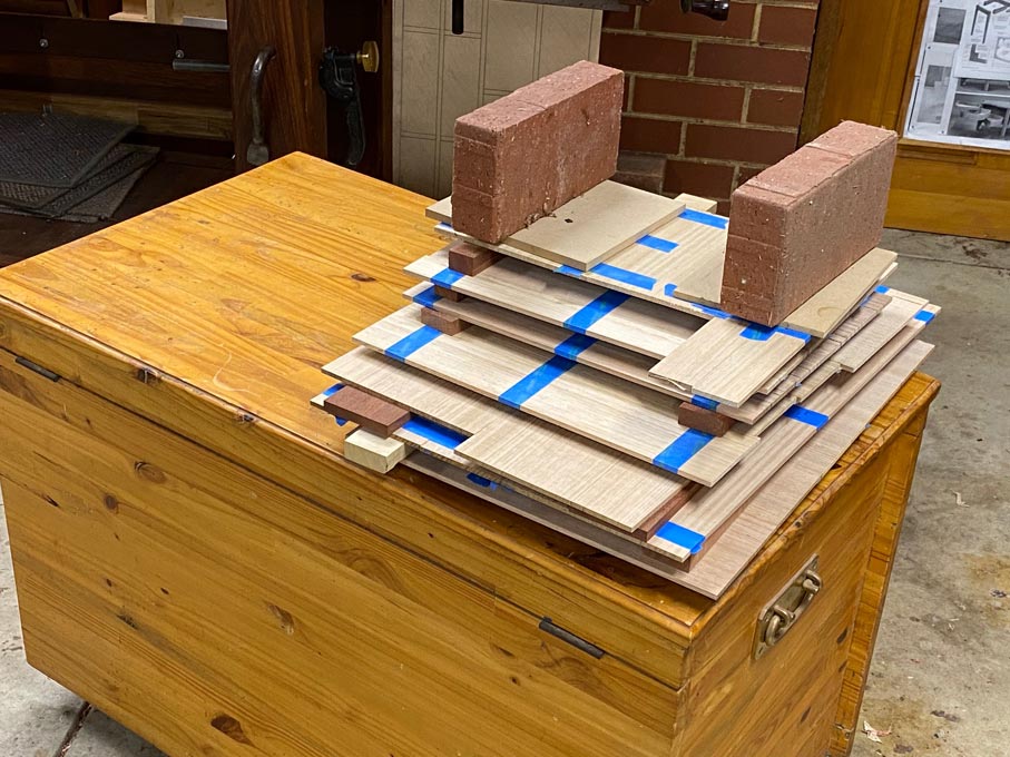
The machining and glueing takes all day, and finally ...

Bottoms-9.jpg


Of course - Murphy's Law - the next day I discover that I am going to be one drawer short, and more offcuts are found and glued together. Smaller pieces this time ...

Bottoms10.jpg


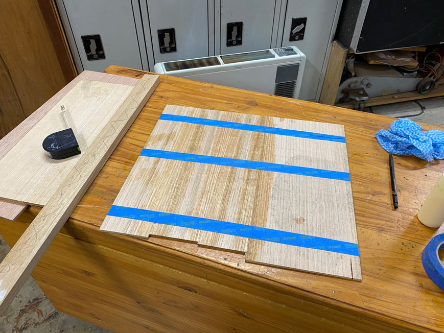
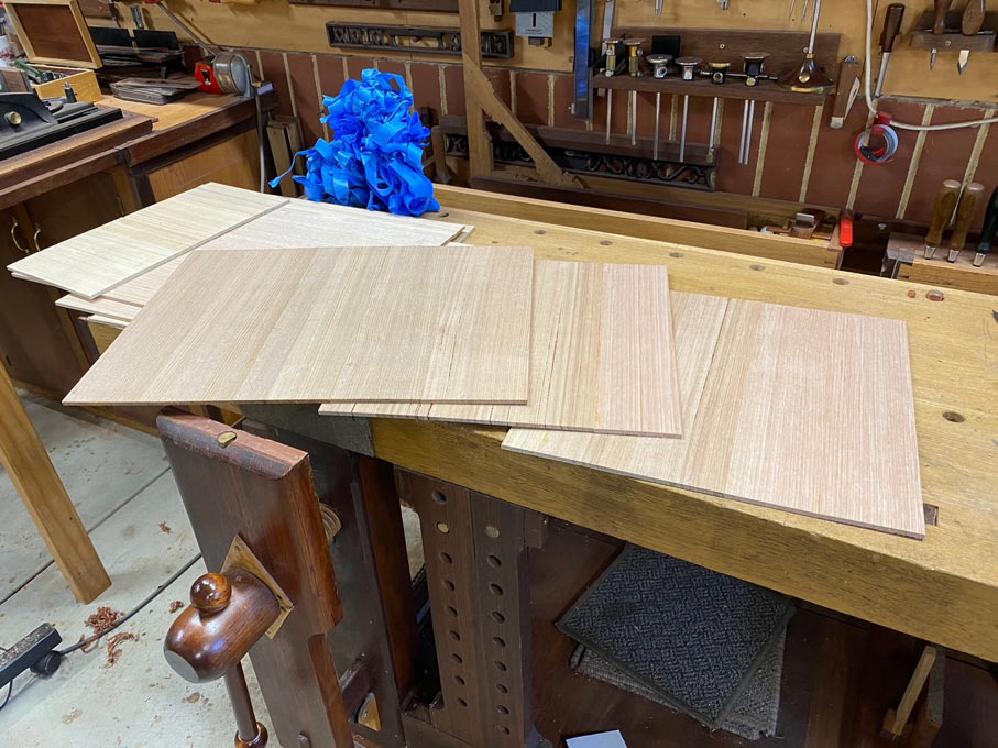
Then it is time to unwrap the presents and make a blue tape Christmas tree ...

Bottoms11.jpg


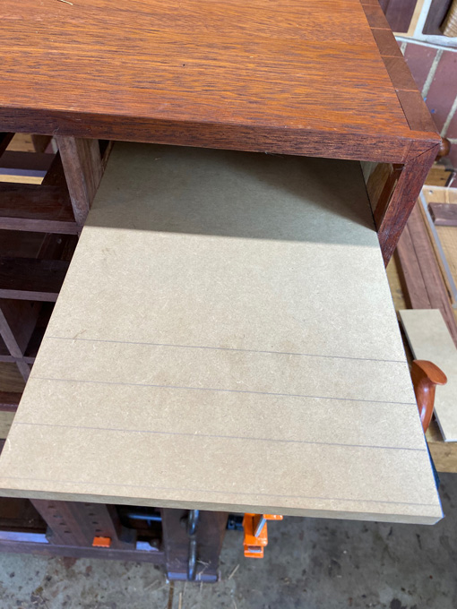
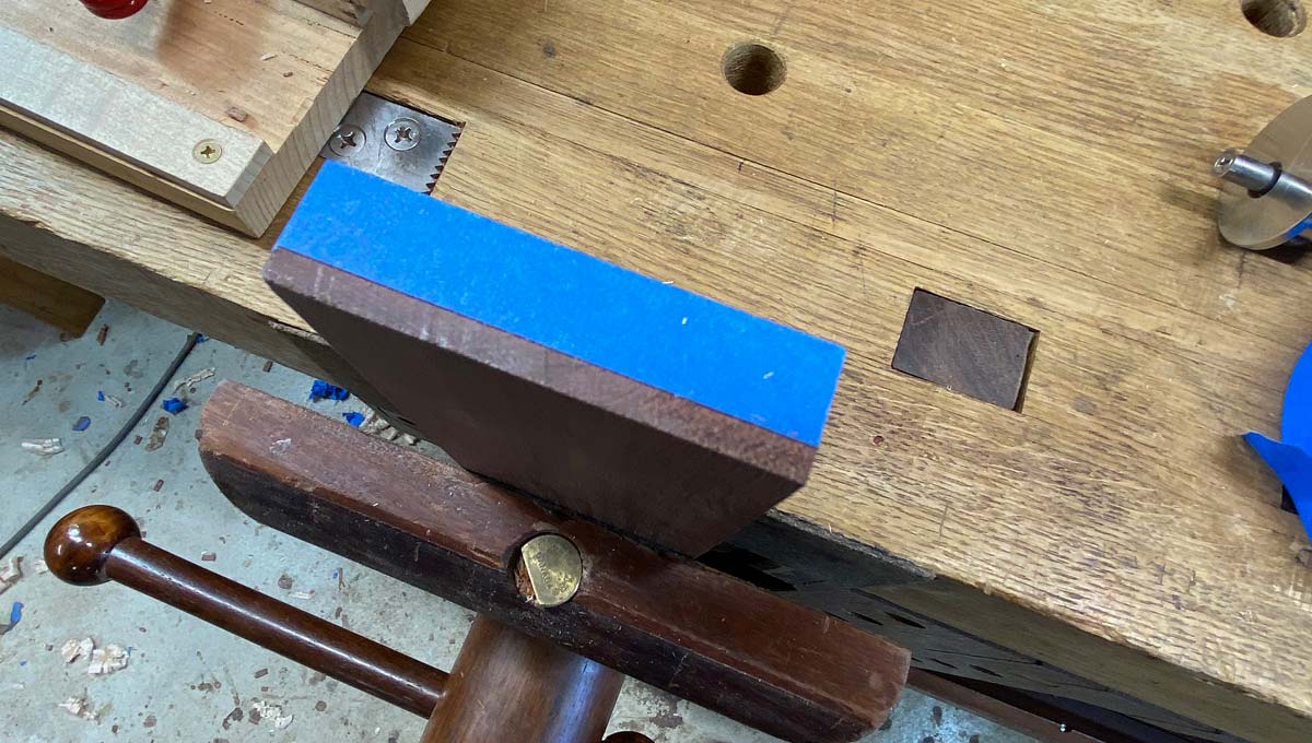
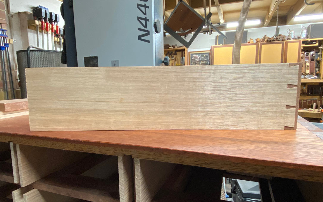
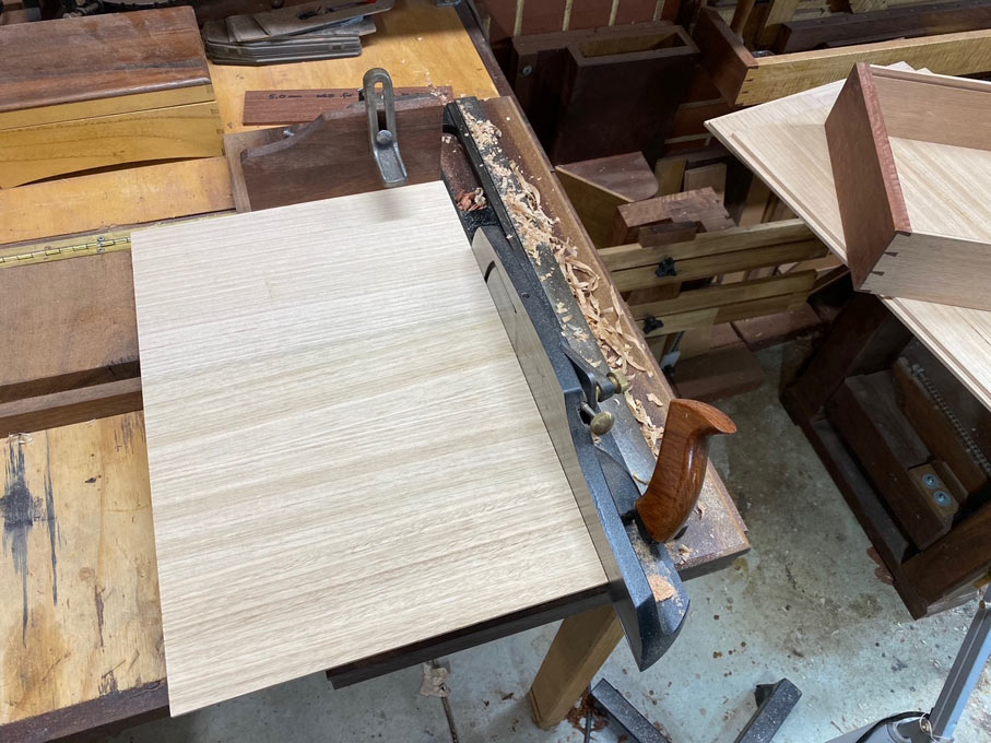
The drawer bottoms are roughly sized, and the top side is sanded to 240 grit (the underside will not be seen, so just leave it be) ...

Bottoms12.jpg


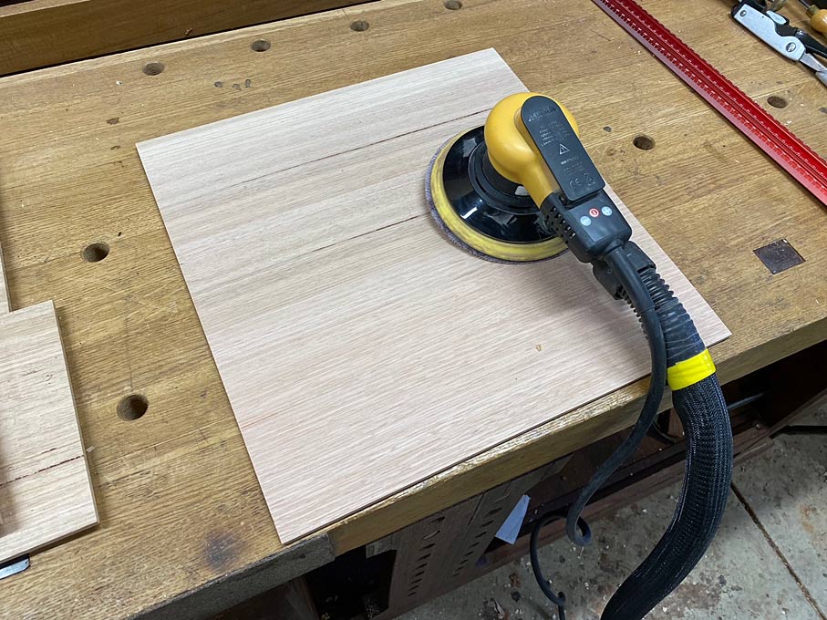
Why sand? Well, it is just easier. The panels are curvy, not flat, and would be too awkward to hand plane. This is what sanders are for. What I have here is a Mirka Ceros, which uses Abranet mesh. Hooked up to a vacuum cleaner, the result is the closest thing to dustless sanding.

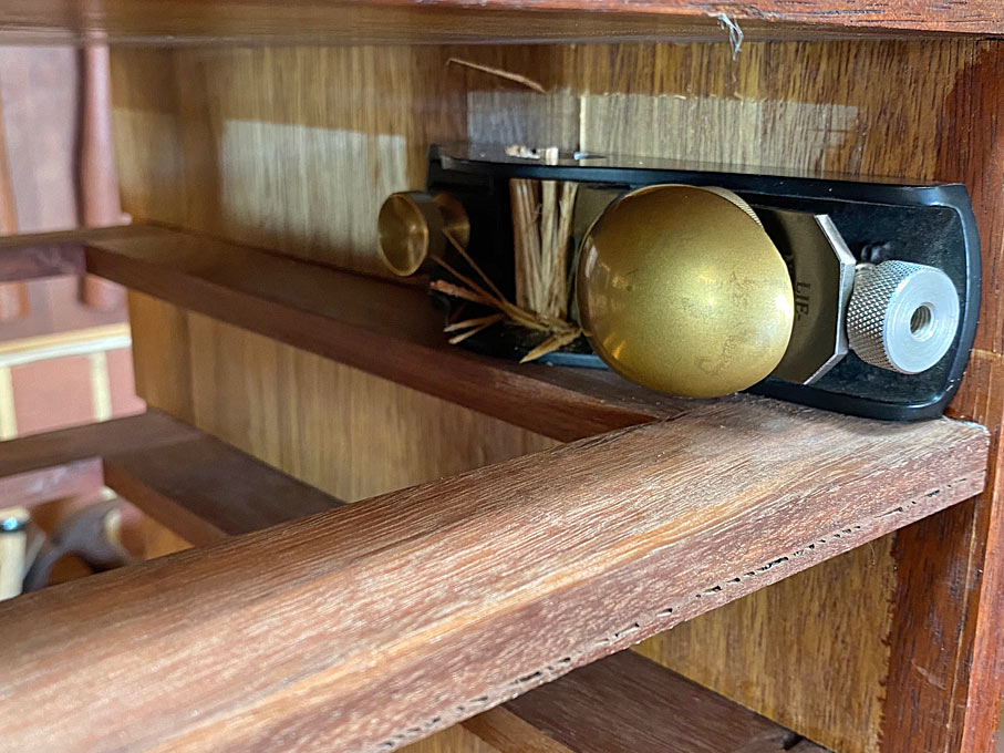
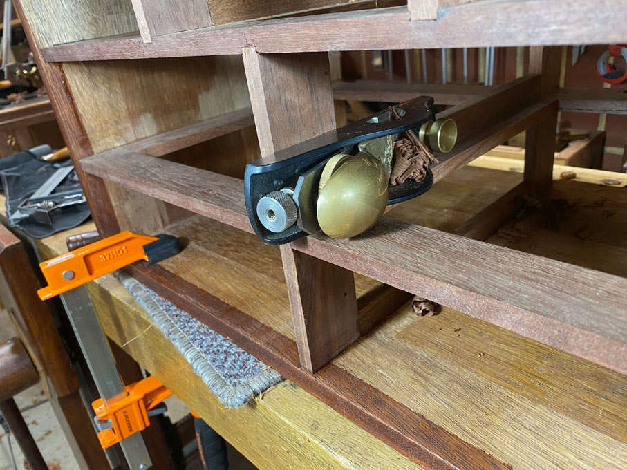
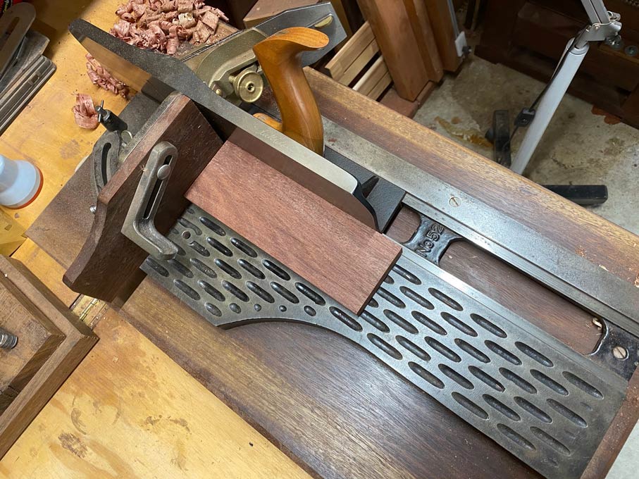
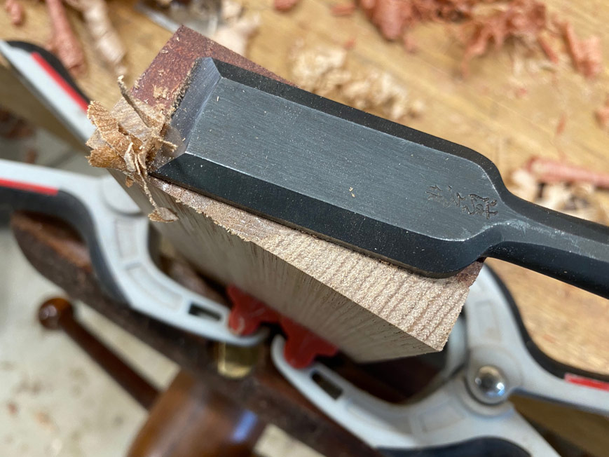
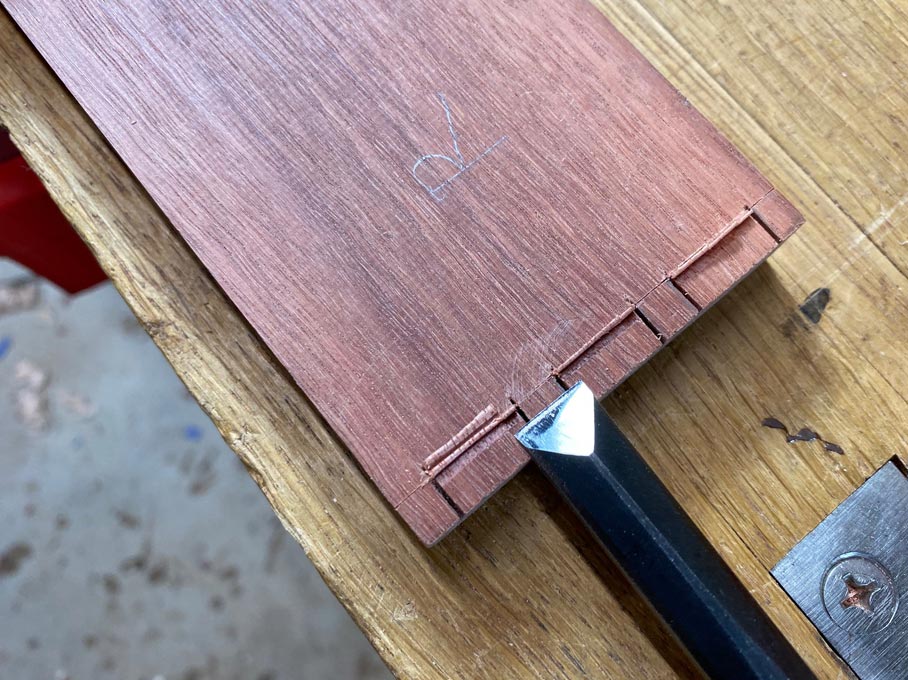
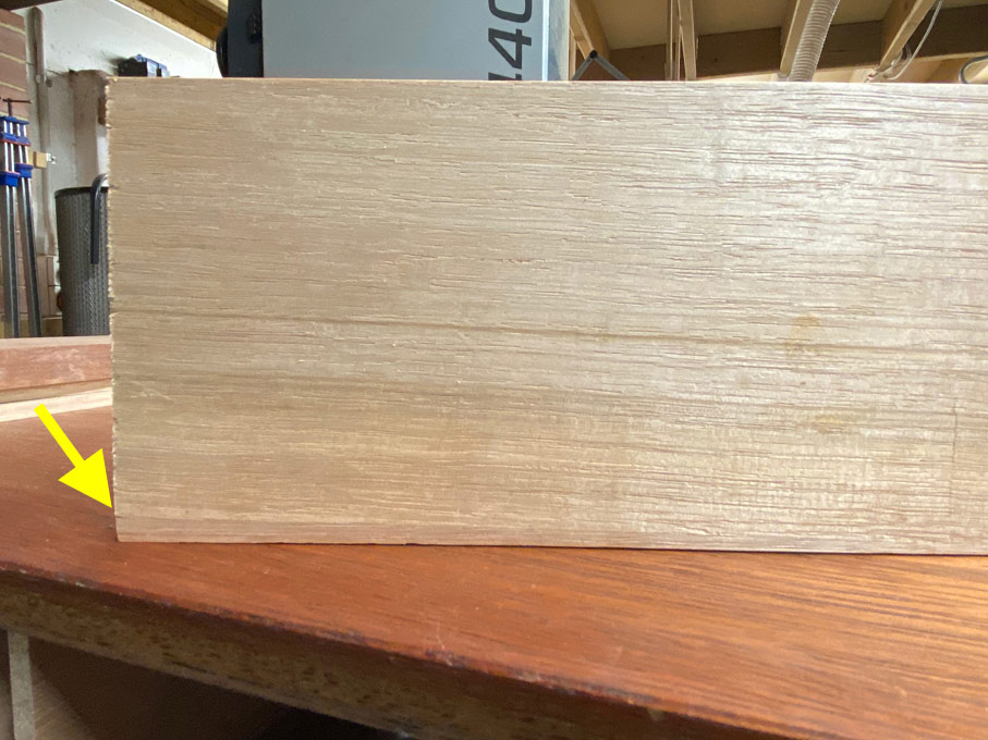
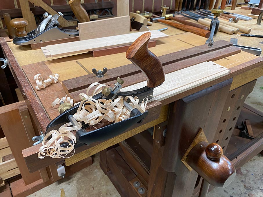
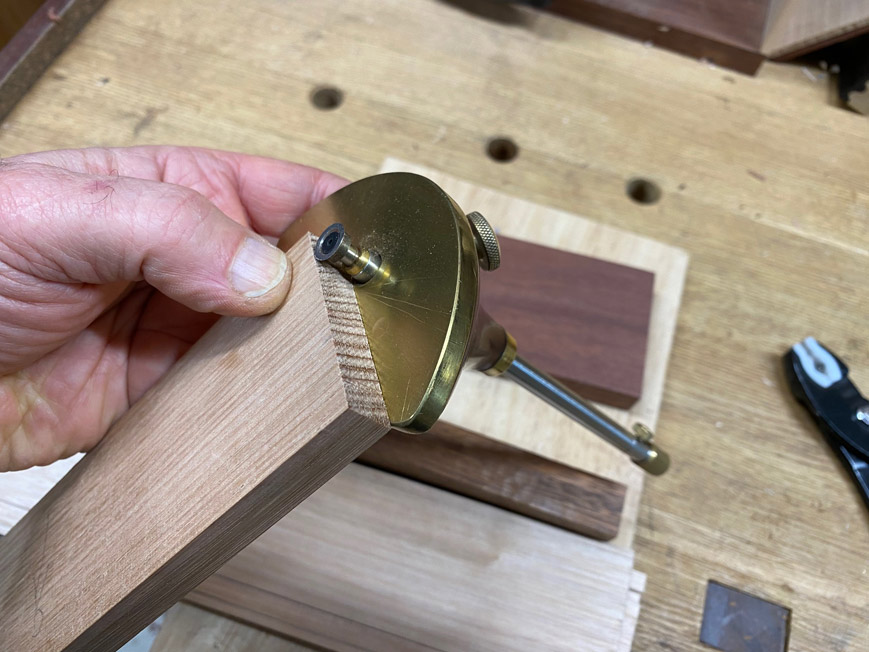
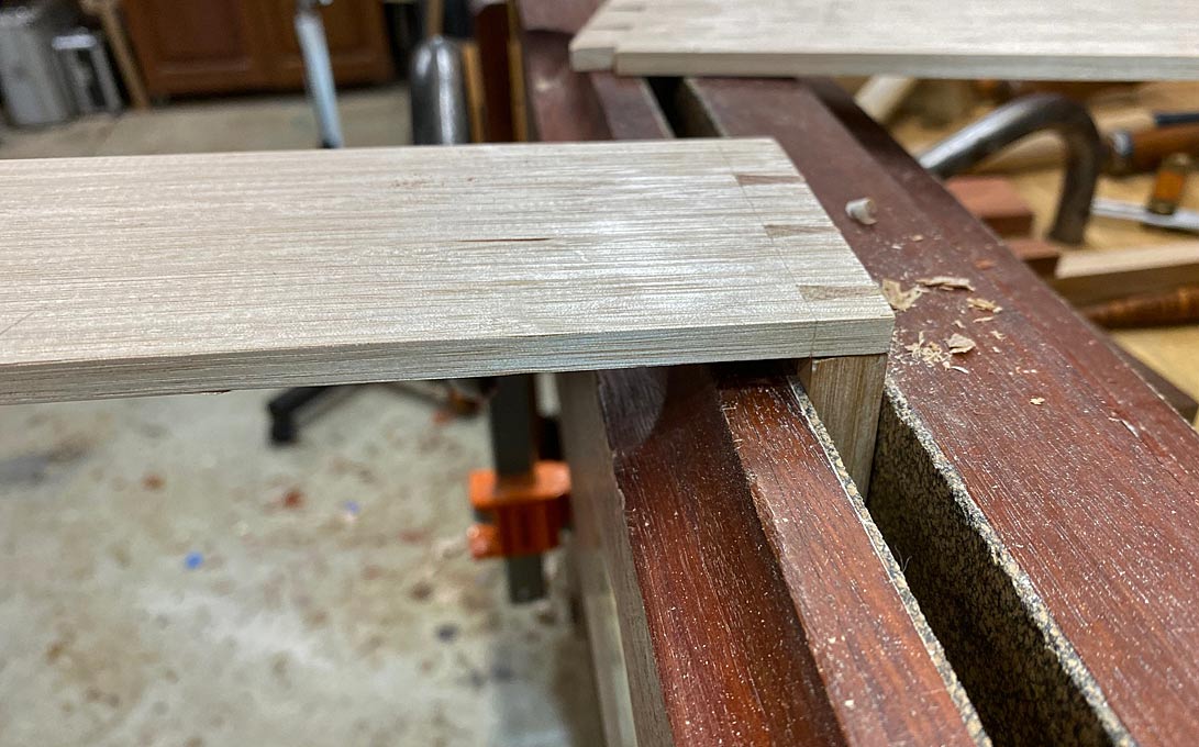
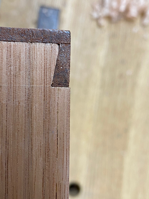
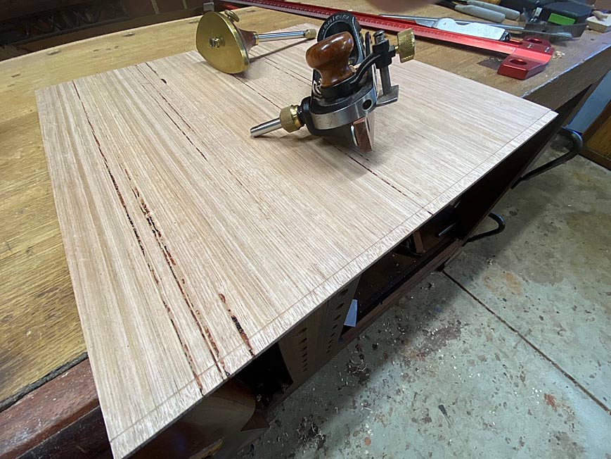
One edge on the underside receives a very shallow rebate. This is to enable the panel to fit the groove. The plane here is a Veritas skew block plane, which has a nicker as it is planing across the grain. It has a fence and a depth stop. Great little plane ..

Bottoms13.jpg


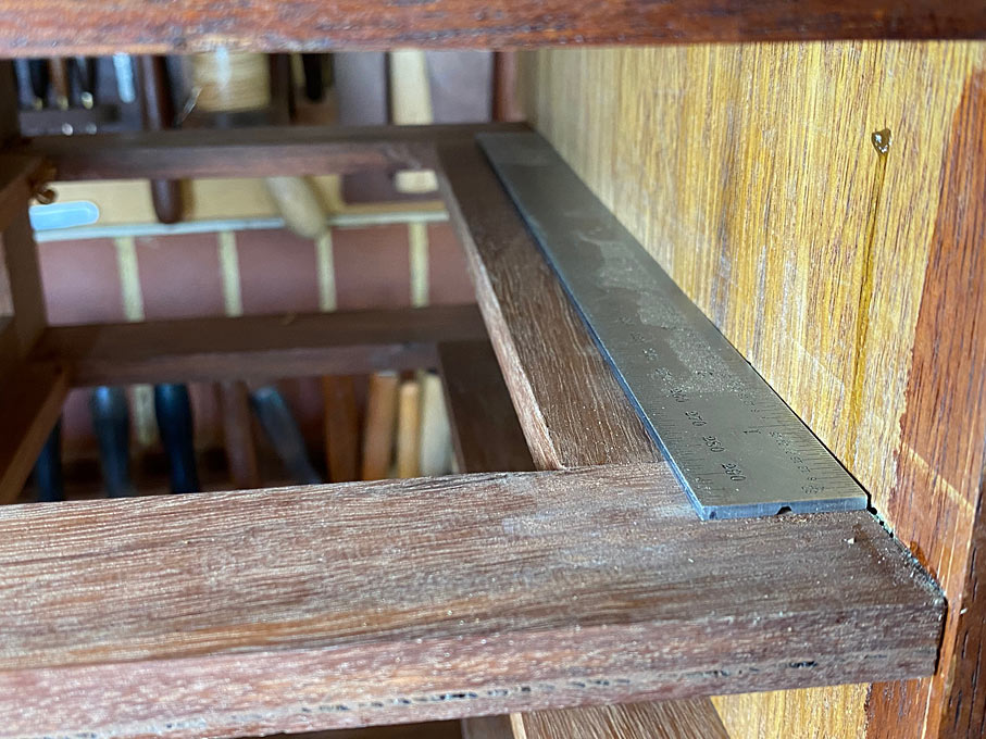
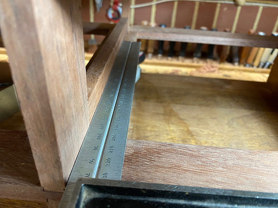
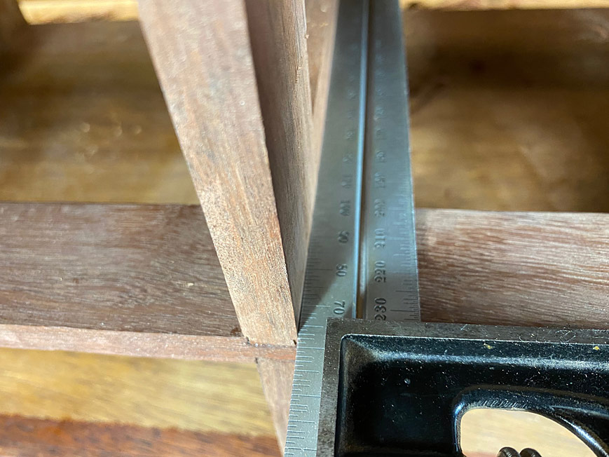
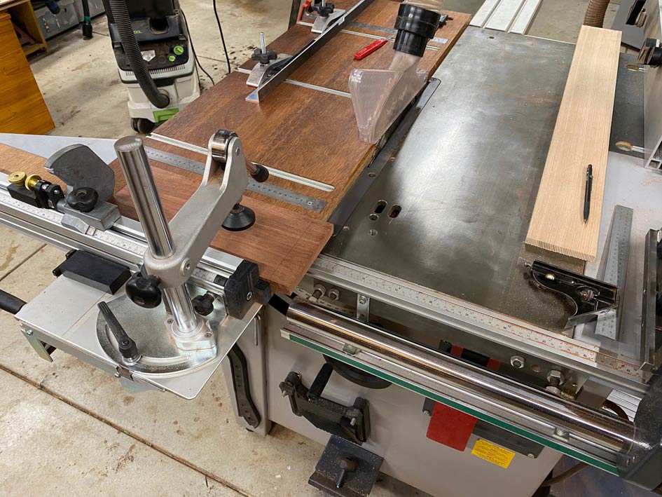
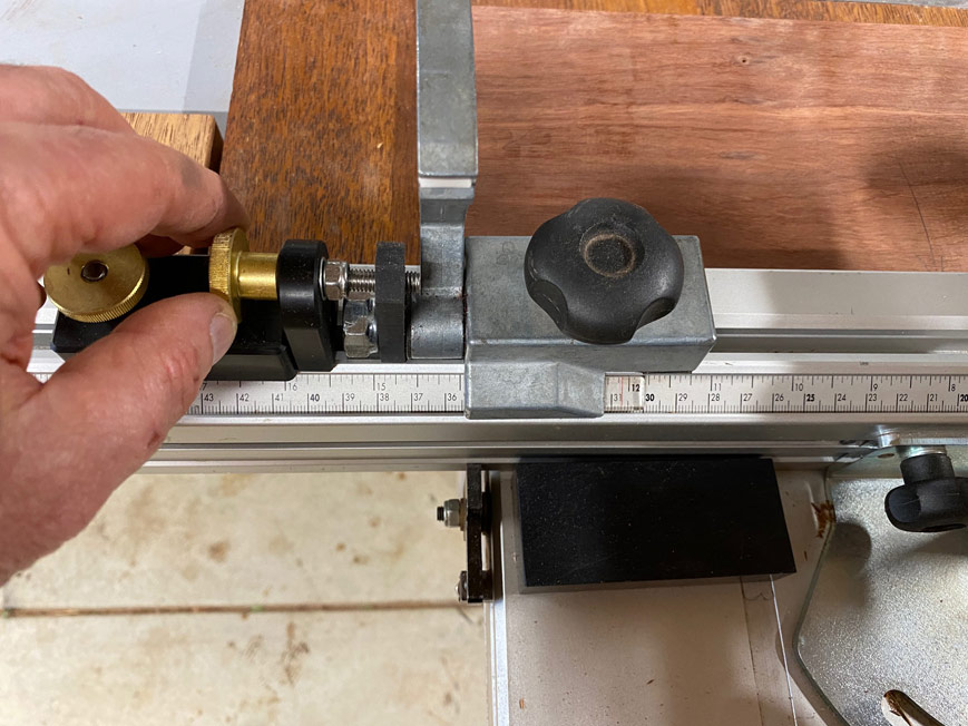
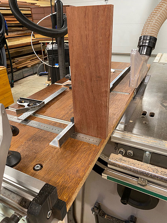
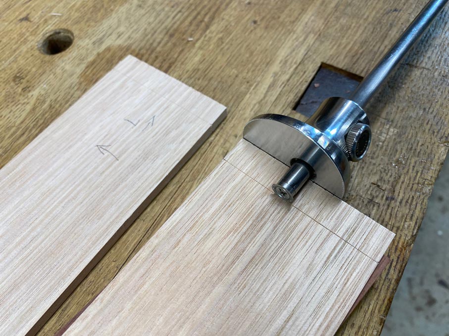
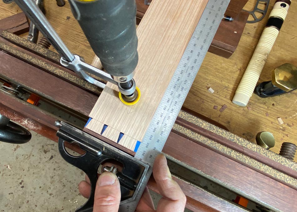
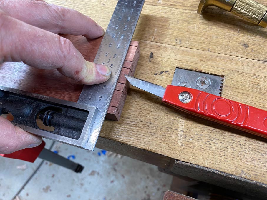
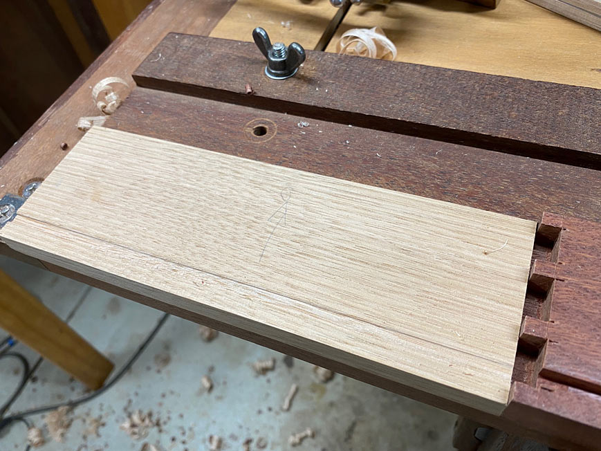
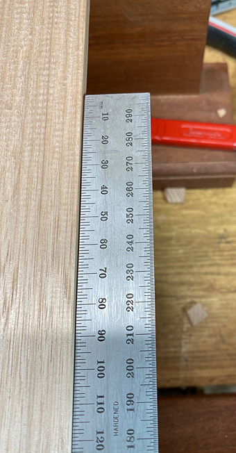
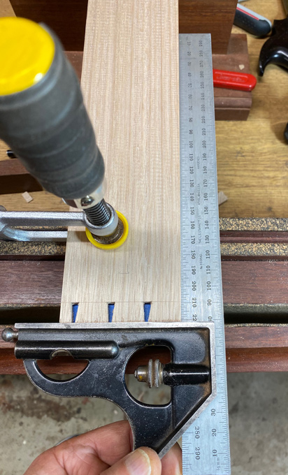
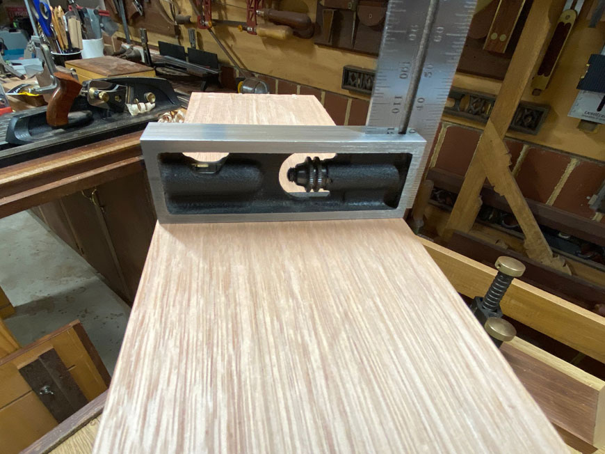
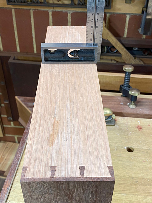
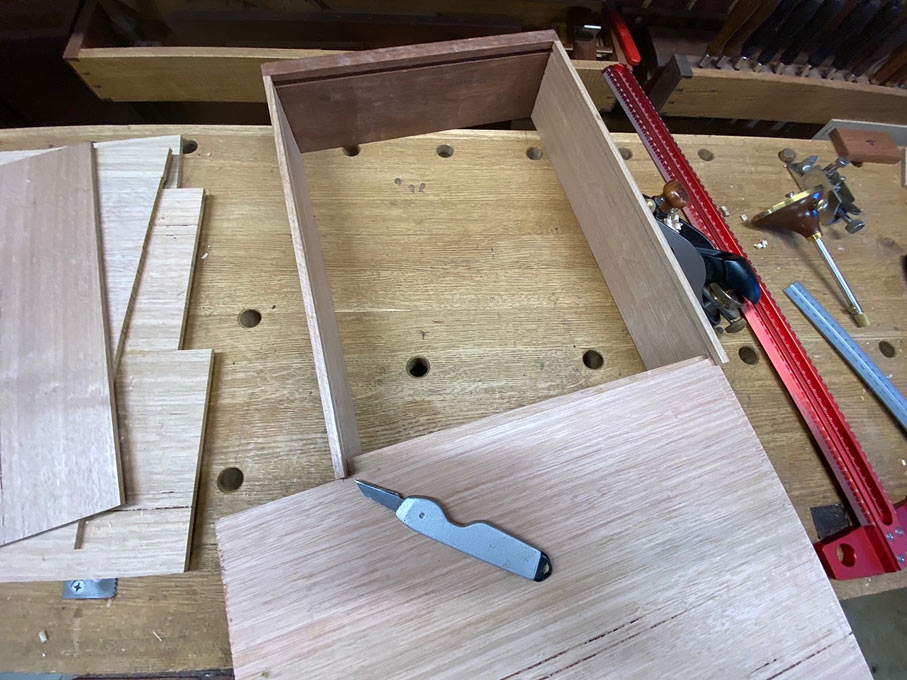
The width of the panel is measured. Note that the drawer bottom runs across the drawer (expansion then takes place front-to-back) ...

Bottoms14.jpg


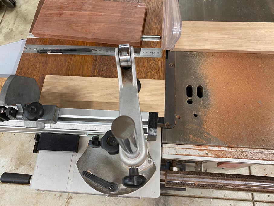
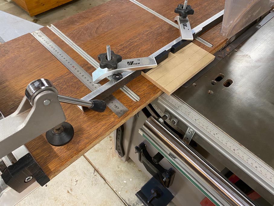
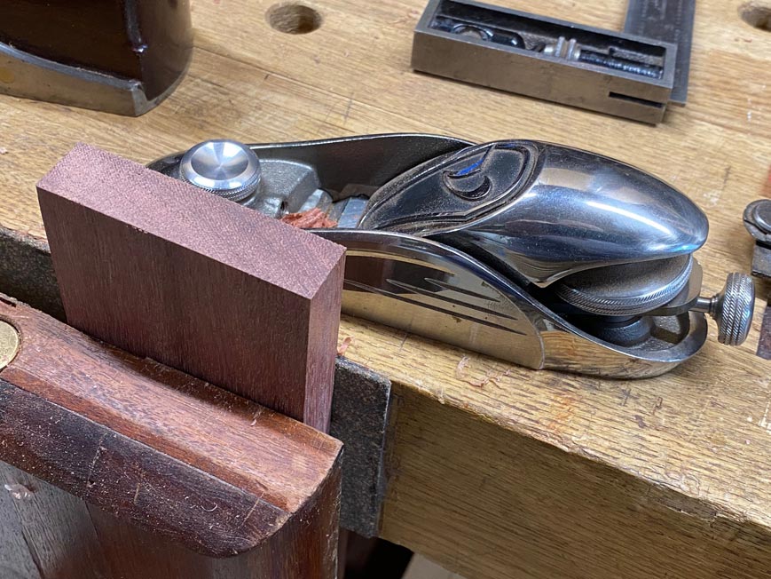
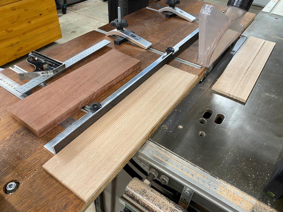
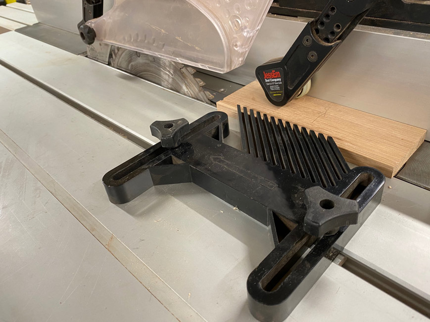
After ripping to size on the table saw, fine tuning takes place with a shooting board ...

Bottoms15.jpg


Time to fit the drawer bottom.

Of course, if it is too tight, it will not run smoothly. But even if it appears to run smoothly, it can be creating a potential problem.

In the earlier chapters (Dovetailing for Blood), one aim was to make the dovetails an exact depth so that the newly glued drawer could dry in the drawer case. The other aim was to fine tune the drawer (minus the drawer bottom) to move smoothly in the drawer case. Now, if when adding the drawer bottom, the smoothness is lost, then we know that something is wrong.

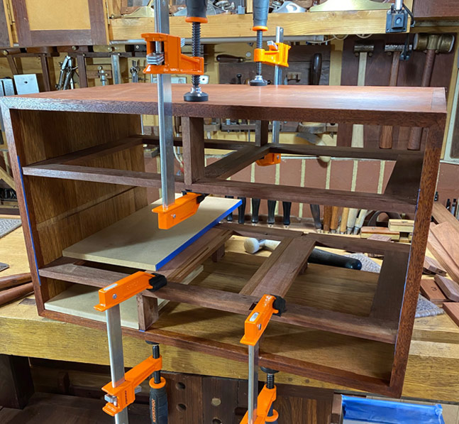
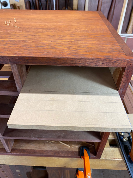
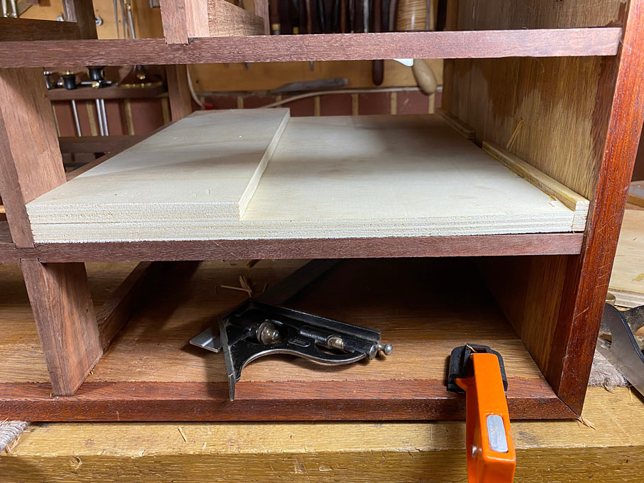
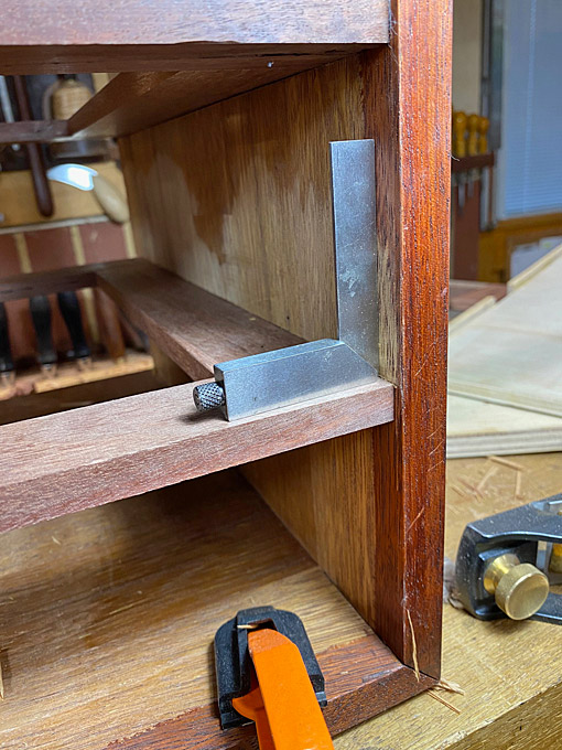
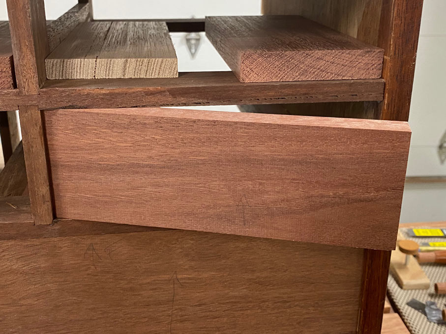
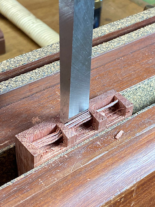
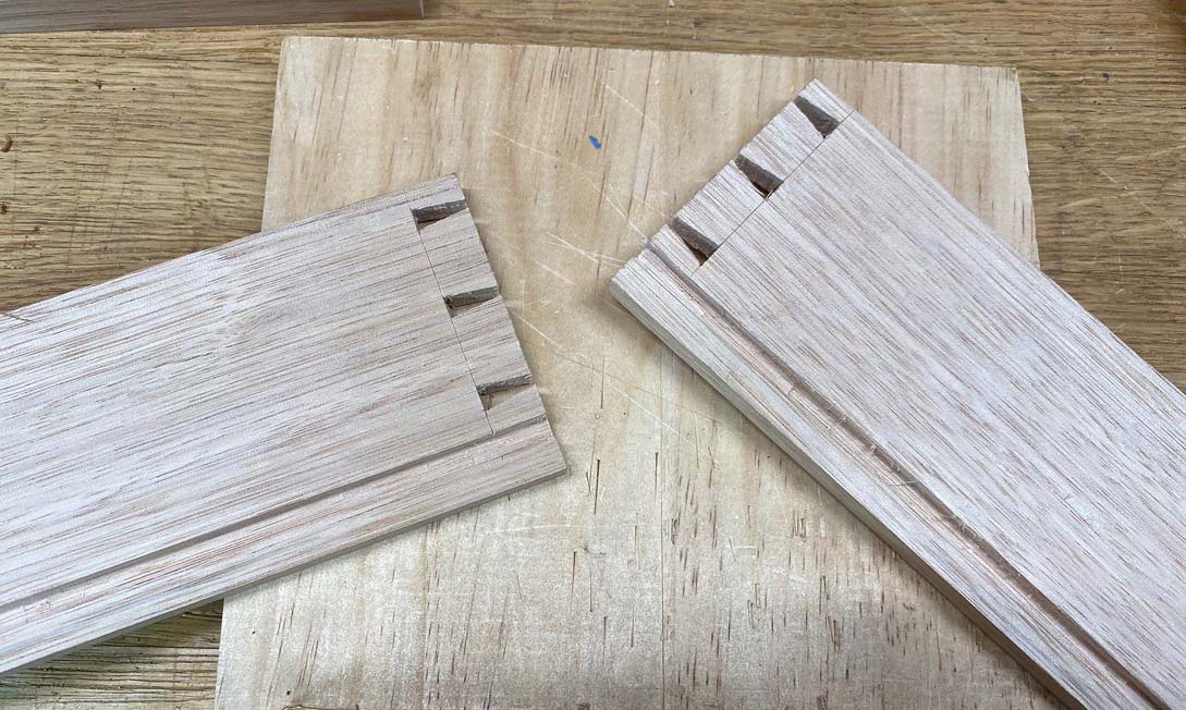
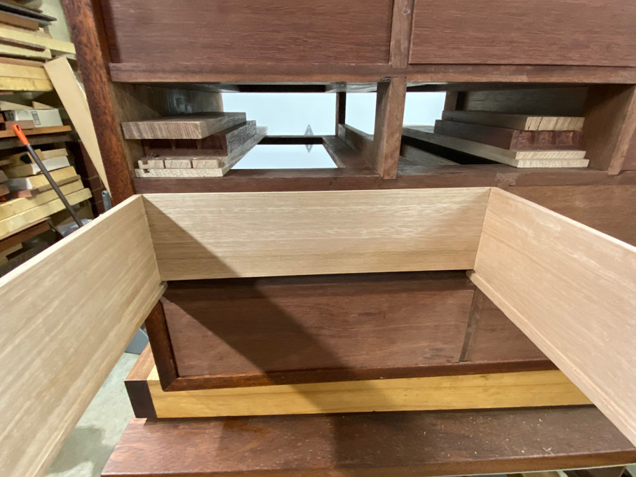
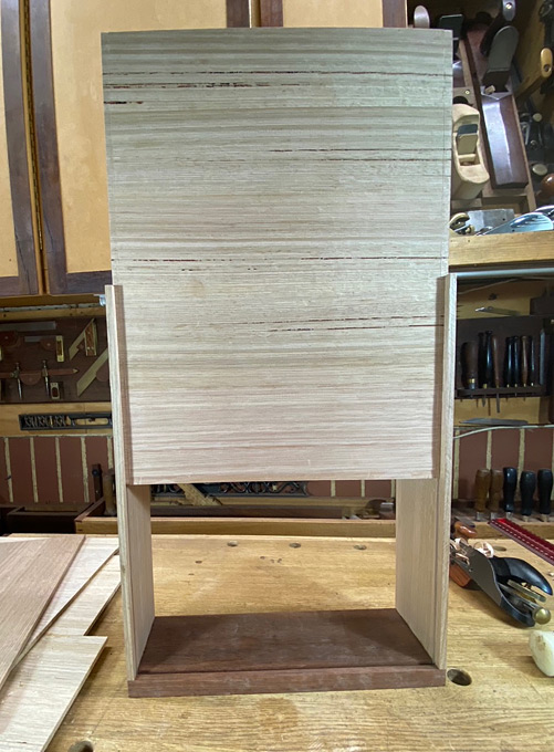
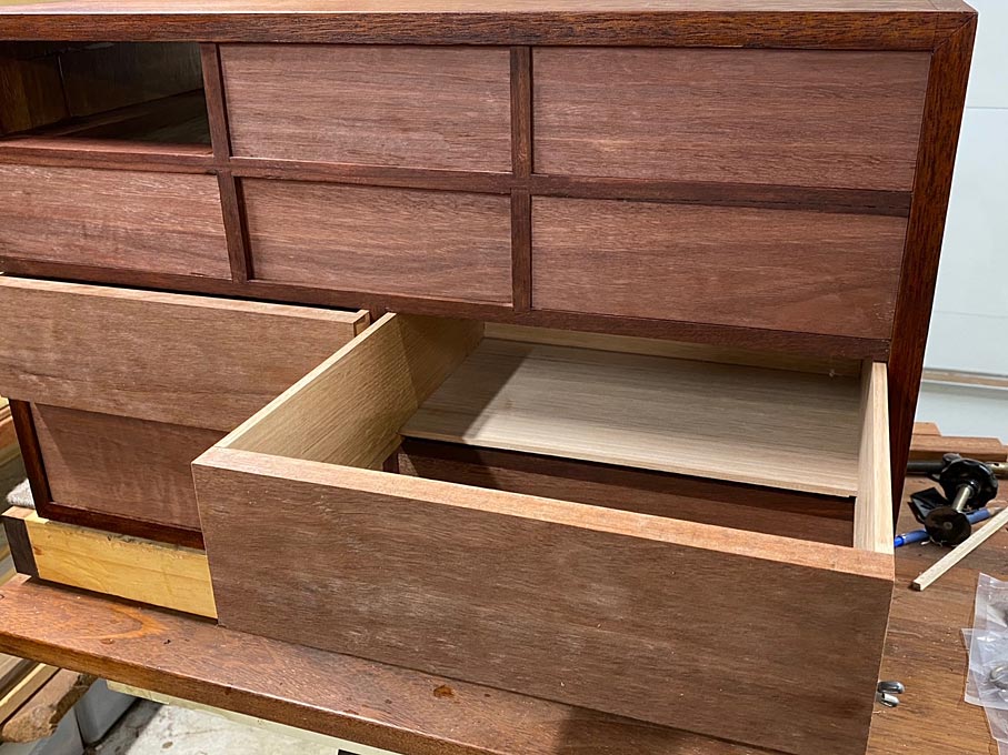
So, the drawer bottom is dropped part way ...

Bottoms16.jpg


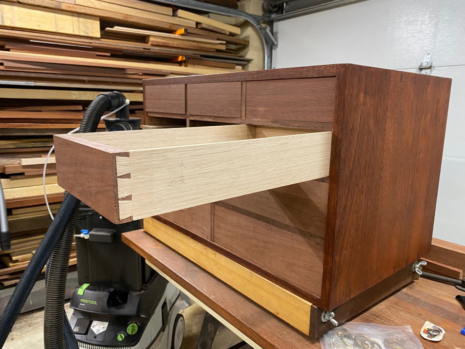
... and this is presented to the drawer case at this point. Will it run as smoothly as before?

Bottoms17.jpg


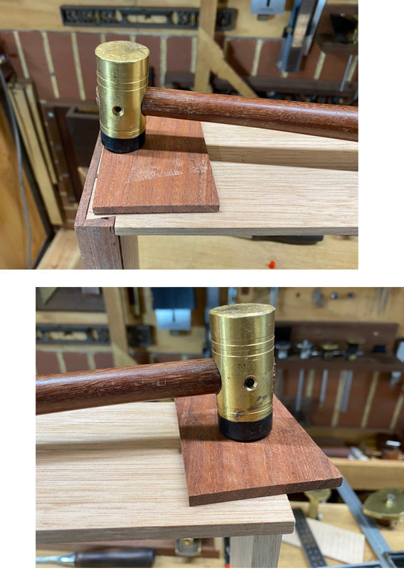
If the drawer appears to have tightened in the case, the problem may be that the sides are slightly bowed. Try tapping the sides to push them flat ...

Bottoms18.jpg


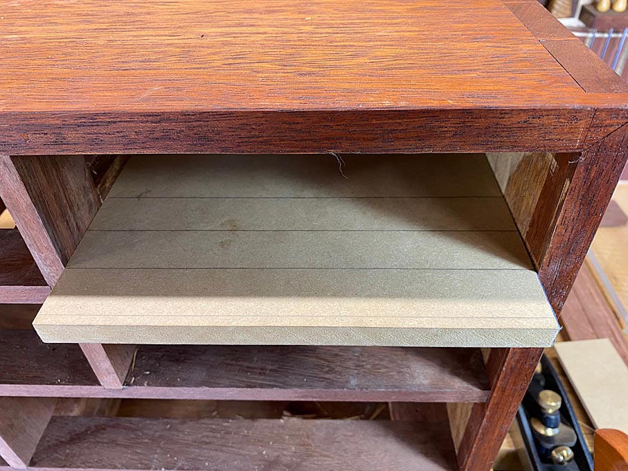
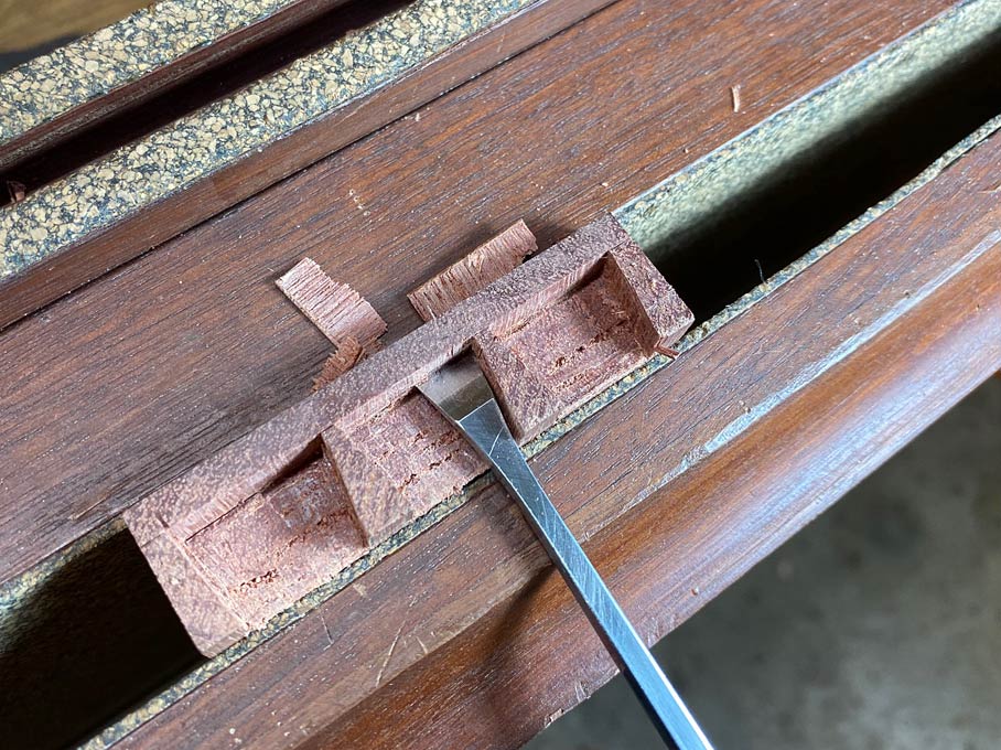
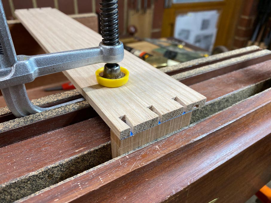
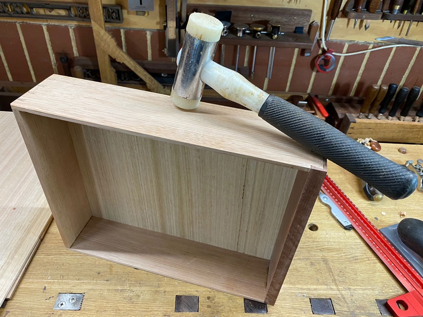
The drawer bottom is lowered further, and again tested for fit ...

Bottoms19.jpg


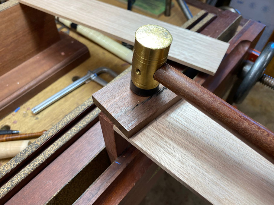
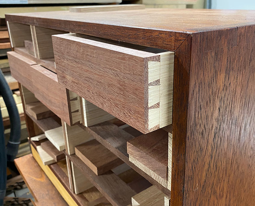
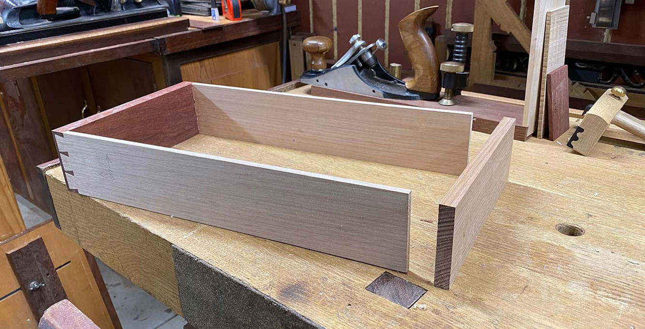
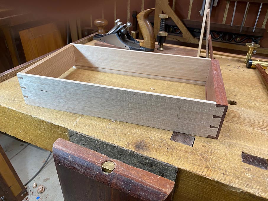
All good, and the bottom is tapped into the groove behind the drawer front. A good fit :)

Bottoms21.jpg


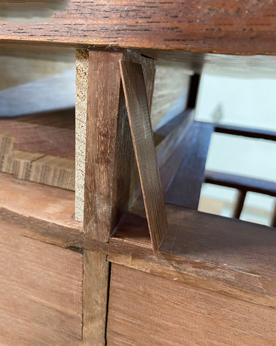
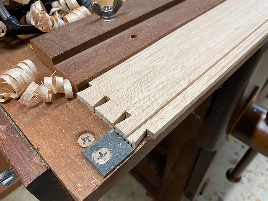
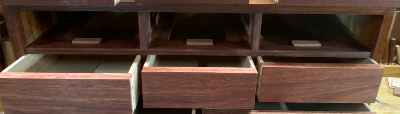
Slips are a traditional way of reinforcing thin drawer sides to increase the surface area and reduce wear over time to the runners. Usually when making slips, I would groove the slip rather than, as here, the drawer side.

Here is one of Richard Jones' wonderful illustrations ...

DrawerDesignandDrawerBottoms_html_4ce48252.jpg


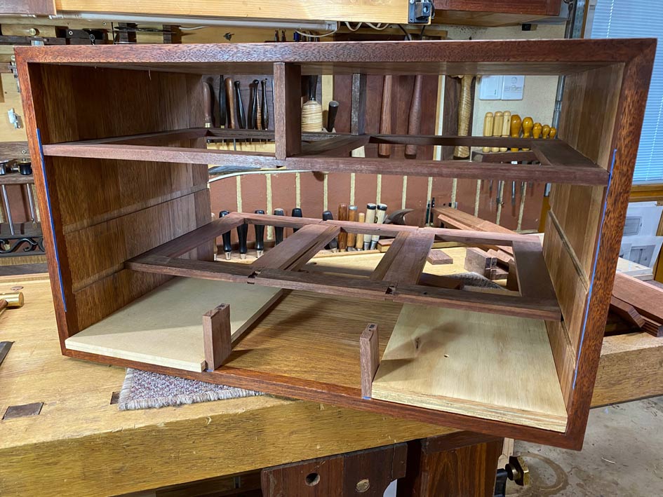
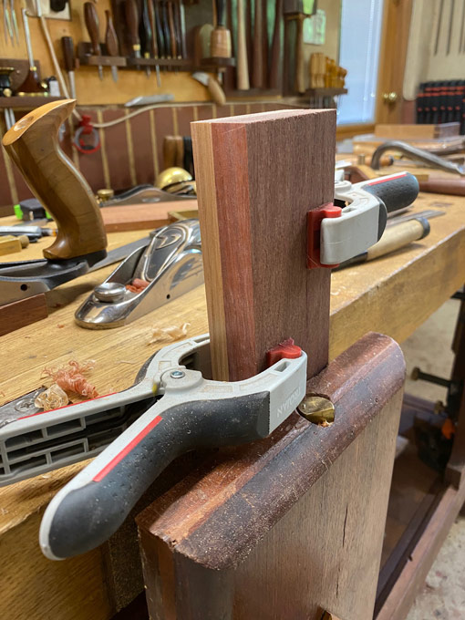
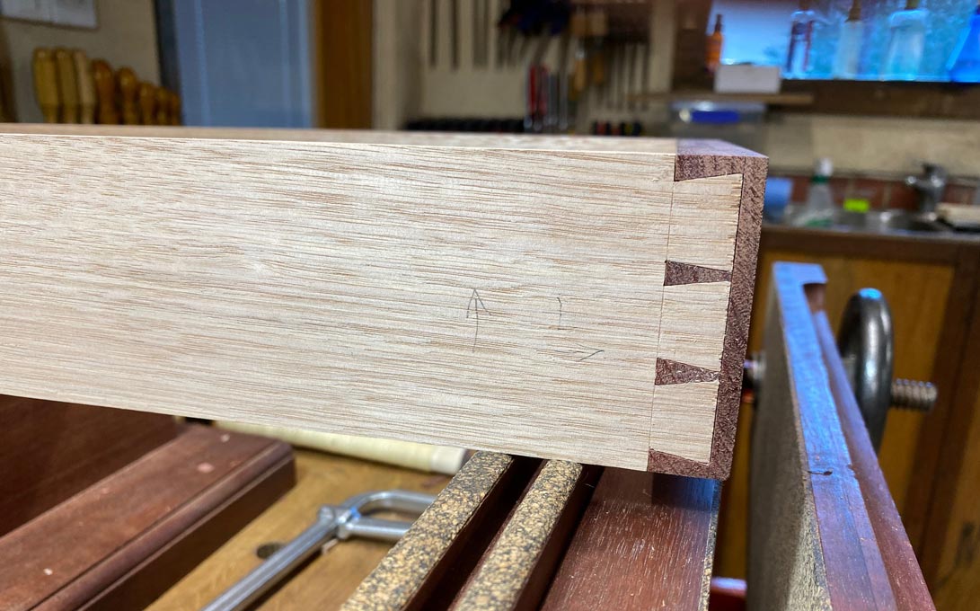
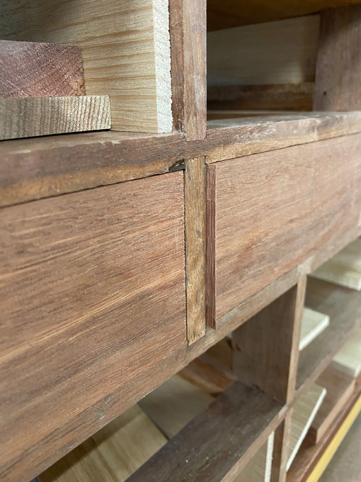
I decided to do something a little different this time. I am not sure whether this can be termed a true slip, but it functions exactly the same way. The drawer sides have a shallow 3mm groove. To support the thin drawer side, as well as support the drawer, a 6mm square Jarrah section was glued to the drawer side directly under the drawer bottom. Care was taken to allow the drawer bottom to remain free to move.

Bottoms22.jpg


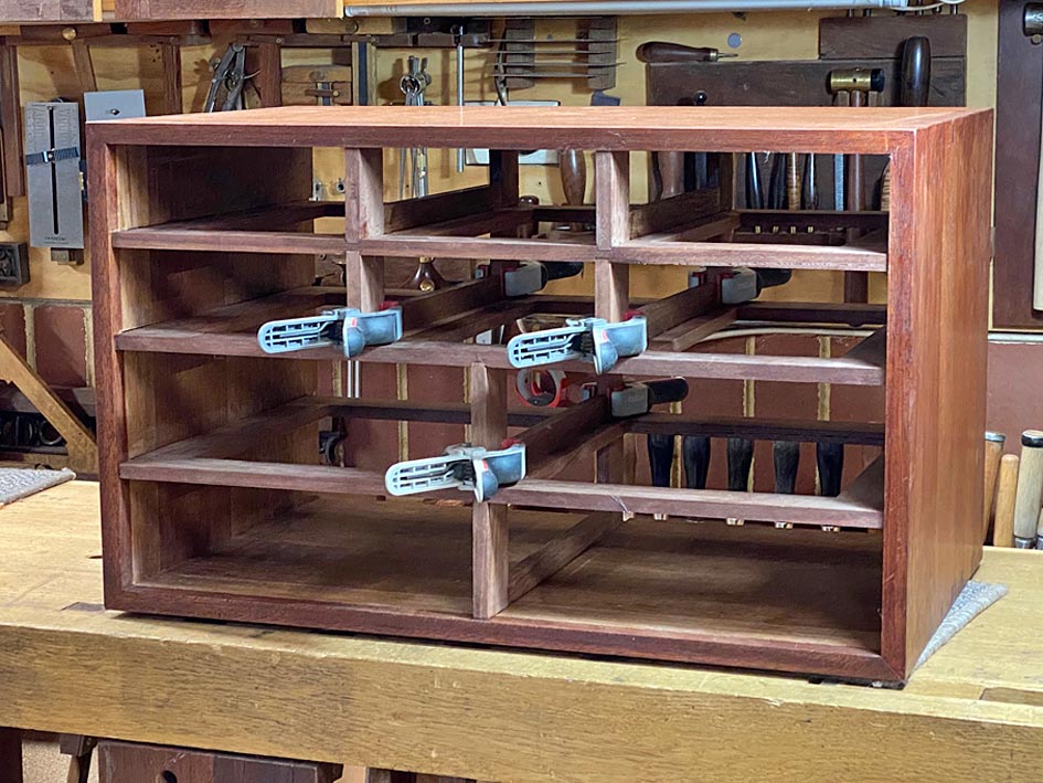
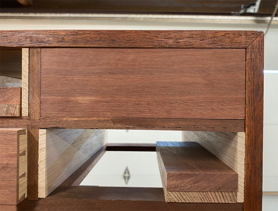
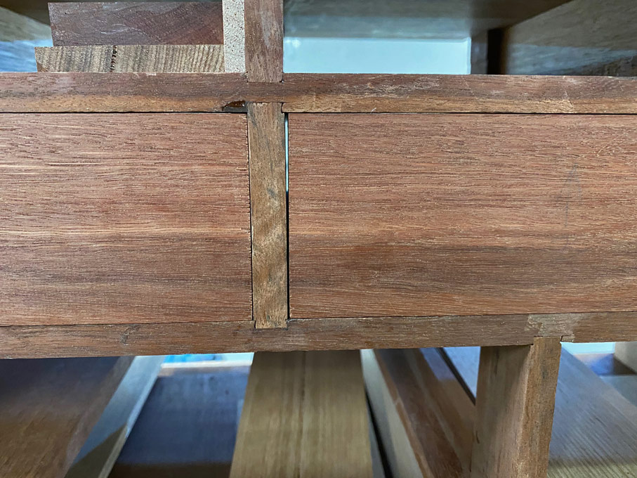
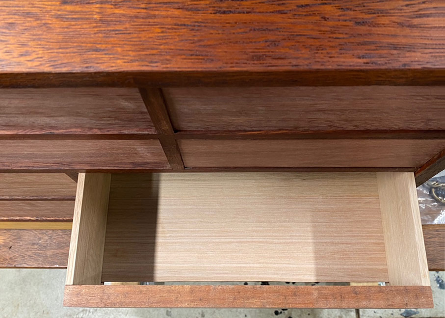
Drawer stops were added ...

Bottoms23.jpg


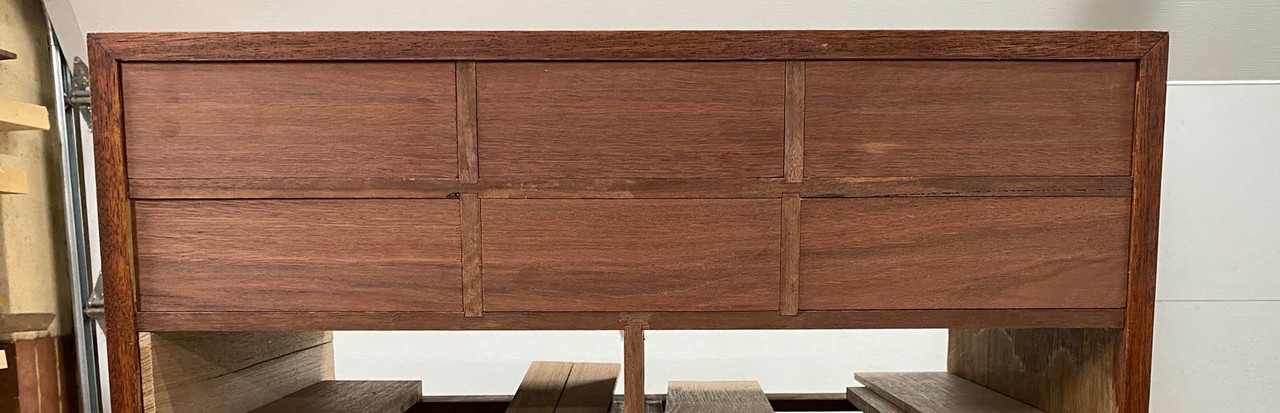
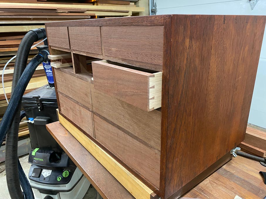
All the drawers fit and move smoothly ...

Bottoms24.jpg


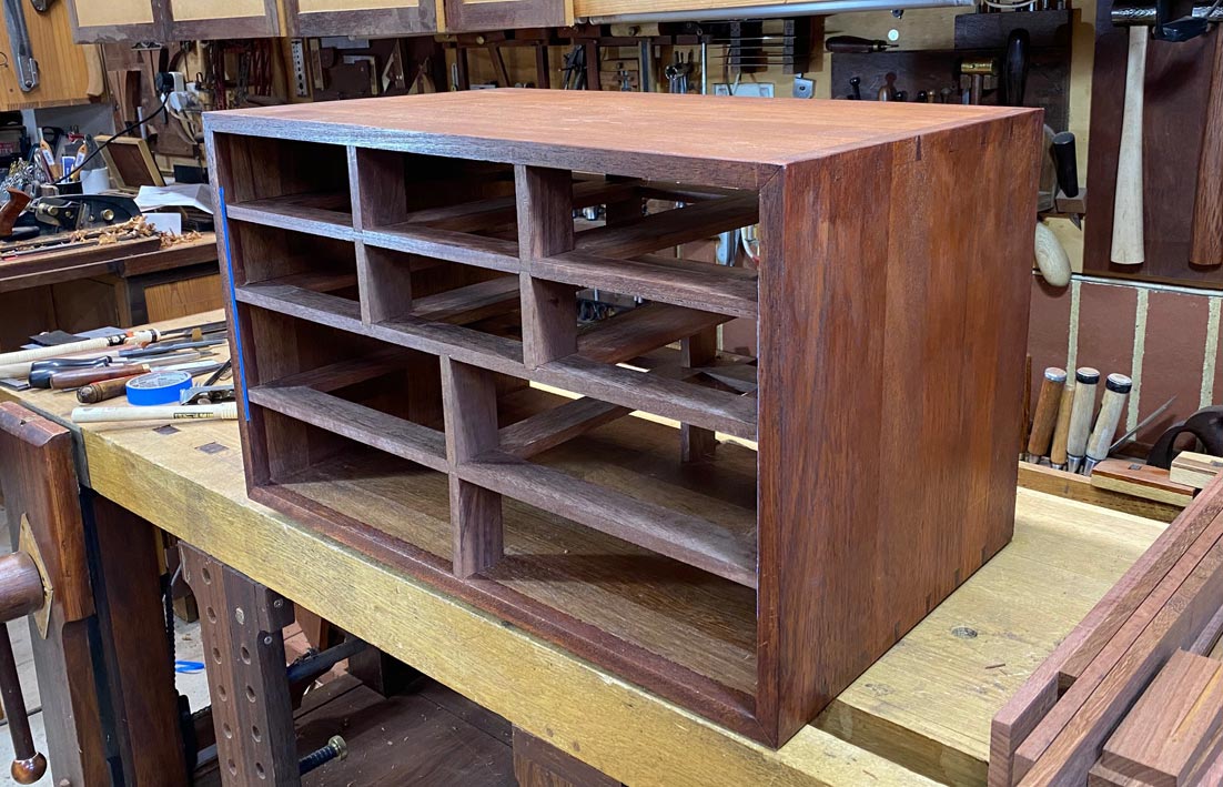
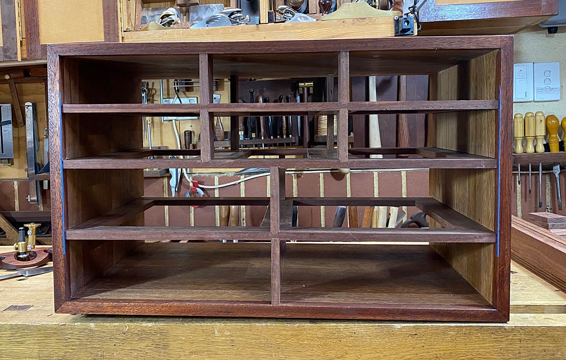
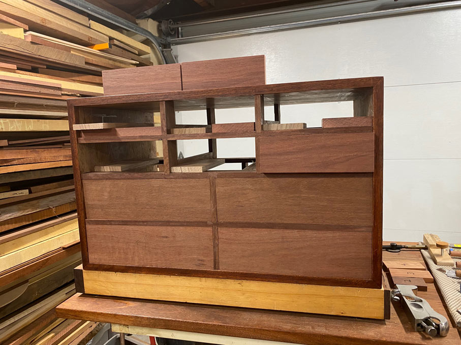
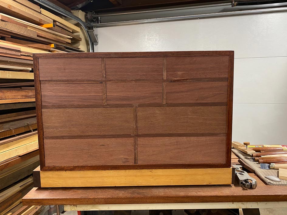
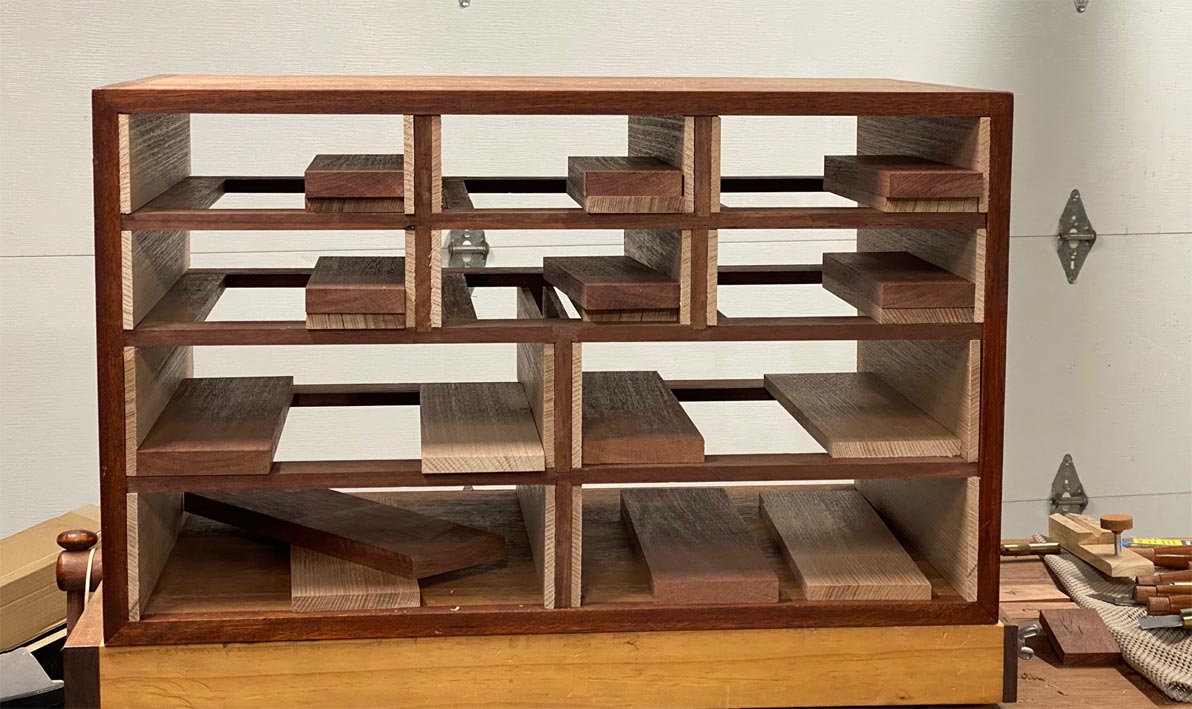
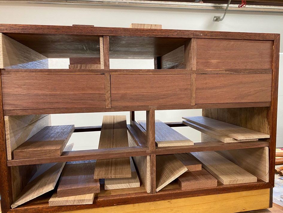
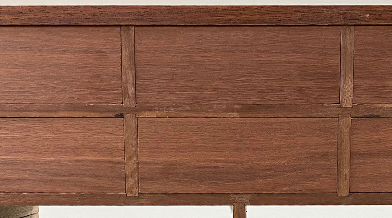
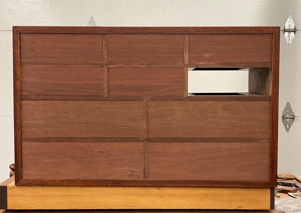
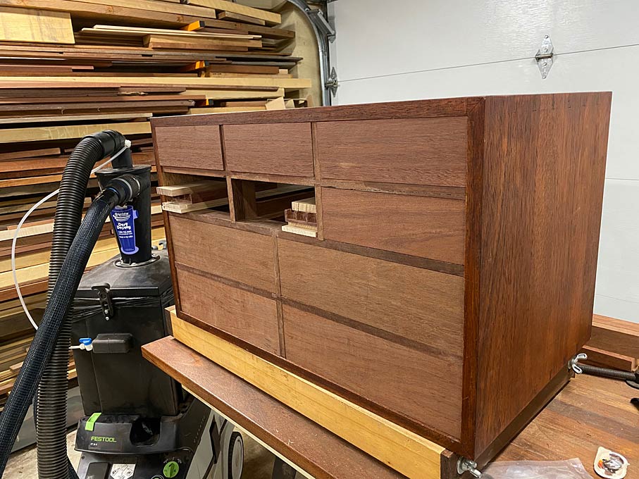
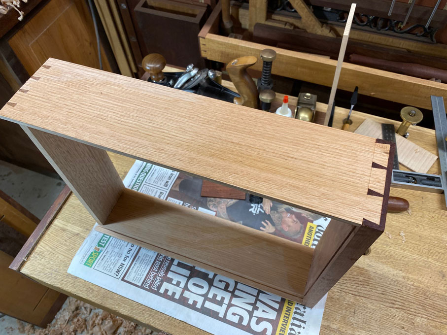
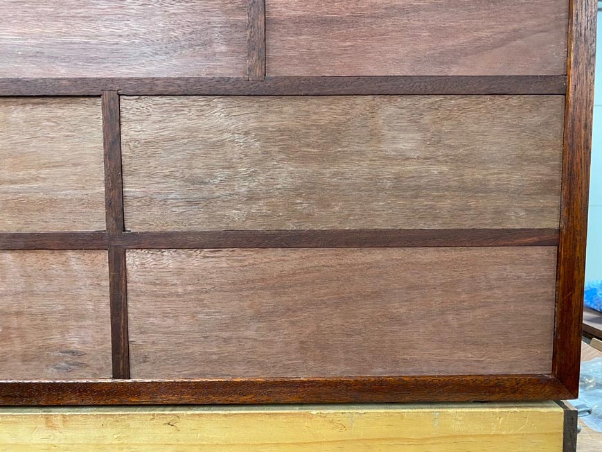
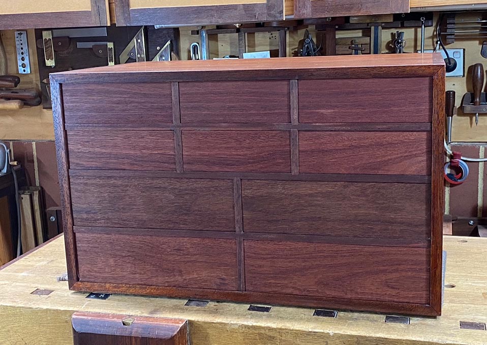
And this is what it looks like at present ...

Bottoms25.jpg


Of course, there is the case back to make, and the handles to fit .... and then the fun bit begins - fitting out each of the 10 drawers for tools. Lots to do still.

Regards from Perth

Derek
 
Back
Top