elviselvis
Member
- Joined
- Jan 25, 2013
- Messages
- 1
Here is guide how to add Vernier scale on Festool`s track parallel guides. It will allows you to set cutting width of your track saw (in my case TS 55 R) very precisely +- 0,05 mm.
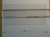
First you have to open attached file "vernier.skp" or "vernier - inverted.skp" in SketchUp application (http://www.sketchup.com/).
Both files are in "vernier.zip" in attachment.
[attachimg=21]
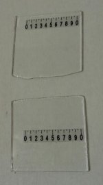
Then print it on A4 paper.
You have to find line, which is closest to 190 mm - cut off this line from paper - we will use only this line.
[attachimg=#]
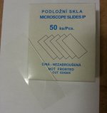
Get some small piece of thin glass - i have used laboratory microscope glass.
[attachimg=#]
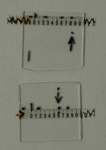
Cut off one piece from paper and glue it to the glass using some transparent glue.
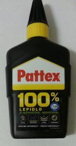
I have used this "Patex" transparent glue to glue paper to glass:
[attachimg=22]
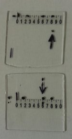
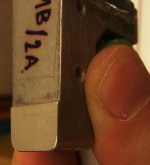
You have to find best location for the piece of paper - each paralel stop will have it in different location, this is little bit tricky to find it.
[attachimg=#]
[attachimg=#]
[attachimg=#]
Use MS Polymer glue and some shims to glue whole glass to paralel stop.
[attachimg=#]
It is also good idea to use alluminium cutting blade on TS55R to improve contact surface on paralel stop, because original surface is not flat. Be carefull when cutting into paralel stop - it can be very dangerous, be sure to use special alluminium cutting blade not the one for wood!. Also be careful how much material you remove, only about 0,1 mm is needed. This is how is looking contact surface on the parallel stop after "miling" with TS55R and alluminium cutting blade.
[attachimg=#]
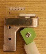
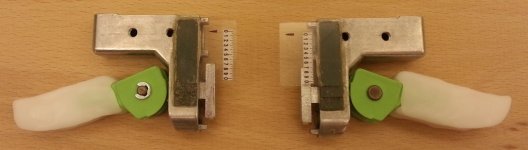
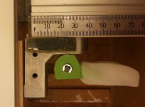
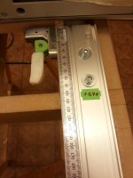
This is how the parallel stop looks after gluing all the shims and glass.
[attachimg=#]
[attachimg=#]
[attachimg=#]
Callibration process:
1) First set it as regular parallel stop by: setting it to 0 mm, unscrew two bolts, touch the blade, tighten two bolts.
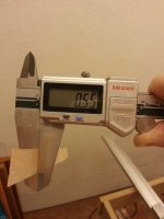
2) Secondly, set it to 1 mm and make cut to some hardwood.
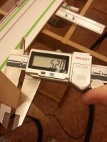
In my case after cut has one side of wood 0,55 mm.
[attachimg=#]
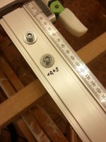
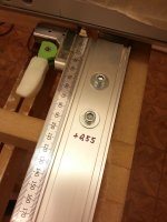
So it mean that next time i will cut, i have to add +0,45 on the scale, because 1,00 - 0,55 = 0,45 mm. So next time if i want to have width of wood 1,00 mm, then i have to set 1,45 mm. I have written this directly on the parallel guide.
[attachimg=#]
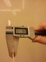
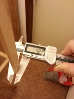
On the second side of wood i measured 0,43 mm.
[attachimg=#]
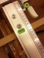
So it mean that next time i will have to add +0,57 mm on scale. Since my Vernier has steps by 0,05 mm, i cant set set it to for example 1,57 mm, i have to set it to the nearest step. In this case i have approximated the value to +0,55. So next time if i want to have width of wood 1,00 mm, then i have to set 1,55 mm. I have written this directly on the parallel guide.
[attachimg=#]
So i continue in callibration process.
This time for better precision i want strip of wood 5,00 mm wide. So i have set first stop to 5,45 mm and second stop to 5,55 mm.
Then i have made a cut.
This is the result on one side of the wood. It resulted width 5,20 mm. So it mean that the correction value +0,45 is too much, i have lowered it to 0,25 mm. I have written this directly on the parallel guide.
[attachimg=#]
[attachimg=#]
On the other side of the wood i have measured 4,83 mm. So it mean that the correction value +0,55 mm is too low, so i have incresed it to +0,70 mm. I have written this directly on the parallel guide.
[attachimg=#]
[attachimg=#]
Then i have made third cut with desired width 5 mm. These are the results:
[attachimg=#]
[attachimg=#]
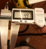
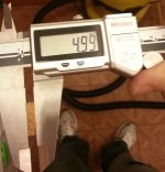
On one side of the wood i have measured 4,97 mm, on the other on side 4,99 mm.
It is pretty precise!!!
So calibration process is finished.
If you want precise results, you have to repeat the calibration process after each assembly of parralel guides to the FS track guide rail. Also each type of wood and each type of cutting blade will have different correction values.
For rough results is recalibration not needed.
Thanks for watching
Jakub Sloup
First you have to open attached file "vernier.skp" or "vernier - inverted.skp" in SketchUp application (http://www.sketchup.com/).
Both files are in "vernier.zip" in attachment.
[attachimg=21]
Then print it on A4 paper.
You have to find line, which is closest to 190 mm - cut off this line from paper - we will use only this line.
[attachimg=#]
Get some small piece of thin glass - i have used laboratory microscope glass.
[attachimg=#]
Cut off one piece from paper and glue it to the glass using some transparent glue.
I have used this "Patex" transparent glue to glue paper to glass:
[attachimg=22]
You have to find best location for the piece of paper - each paralel stop will have it in different location, this is little bit tricky to find it.
[attachimg=#]
[attachimg=#]
[attachimg=#]
Use MS Polymer glue and some shims to glue whole glass to paralel stop.
[attachimg=#]
It is also good idea to use alluminium cutting blade on TS55R to improve contact surface on paralel stop, because original surface is not flat. Be carefull when cutting into paralel stop - it can be very dangerous, be sure to use special alluminium cutting blade not the one for wood!. Also be careful how much material you remove, only about 0,1 mm is needed. This is how is looking contact surface on the parallel stop after "miling" with TS55R and alluminium cutting blade.
[attachimg=#]
This is how the parallel stop looks after gluing all the shims and glass.
[attachimg=#]
[attachimg=#]
[attachimg=#]
Callibration process:
1) First set it as regular parallel stop by: setting it to 0 mm, unscrew two bolts, touch the blade, tighten two bolts.
2) Secondly, set it to 1 mm and make cut to some hardwood.
In my case after cut has one side of wood 0,55 mm.
[attachimg=#]
So it mean that next time i will cut, i have to add +0,45 on the scale, because 1,00 - 0,55 = 0,45 mm. So next time if i want to have width of wood 1,00 mm, then i have to set 1,45 mm. I have written this directly on the parallel guide.
[attachimg=#]
On the second side of wood i measured 0,43 mm.
[attachimg=#]
So it mean that next time i will have to add +0,57 mm on scale. Since my Vernier has steps by 0,05 mm, i cant set set it to for example 1,57 mm, i have to set it to the nearest step. In this case i have approximated the value to +0,55. So next time if i want to have width of wood 1,00 mm, then i have to set 1,55 mm. I have written this directly on the parallel guide.
[attachimg=#]
So i continue in callibration process.
This time for better precision i want strip of wood 5,00 mm wide. So i have set first stop to 5,45 mm and second stop to 5,55 mm.
Then i have made a cut.
This is the result on one side of the wood. It resulted width 5,20 mm. So it mean that the correction value +0,45 is too much, i have lowered it to 0,25 mm. I have written this directly on the parallel guide.
[attachimg=#]
[attachimg=#]
On the other side of the wood i have measured 4,83 mm. So it mean that the correction value +0,55 mm is too low, so i have incresed it to +0,70 mm. I have written this directly on the parallel guide.
[attachimg=#]
[attachimg=#]
Then i have made third cut with desired width 5 mm. These are the results:
[attachimg=#]
[attachimg=#]
On one side of the wood i have measured 4,97 mm, on the other on side 4,99 mm.
It is pretty precise!!!
So calibration process is finished.
If you want precise results, you have to repeat the calibration process after each assembly of parralel guides to the FS track guide rail. Also each type of wood and each type of cutting blade will have different correction values.
For rough results is recalibration not needed.
Thanks for watching
Jakub Sloup
Attachments
-
 001.jpg310.6 KB · Views: 1,229
 -
 002.jpg127.8 KB · Views: 1,182
 -
 003.jpg396.5 KB · Views: 1,248
 -
 004.jpg306.5 KB · Views: 1,156
 -
 005.jpg314.4 KB · Views: 1,170
 -
 006.jpg124 KB · Views: 1,154
 -
 007.jpg156 KB · Views: 1,175
 -
 008.jpg154.7 KB · Views: 1,286
 -
 010.jpg99.2 KB · Views: 1,165
 -
 011.jpg235.3 KB · Views: 1,177
 -
 020.jpg169.1 KB · Views: 1,130
 -
 021.jpg254.5 KB · Views: 1,178
 -
 022.jpg132.6 KB · Views: 1,150
 -
 023.jpg239.6 KB · Views: 1,172
 -
 030.jpg193.3 KB · Views: 1,151
 -
 031.jpg260.4 KB · Views: 1,141
 -
 032.jpg167.5 KB · Views: 1,112
 -
 033.jpg224.5 KB · Views: 1,109
 -
 040.jpg169 KB · Views: 1,193
 -
 041.jpg141.2 KB · Views: 1,208
 -
vernier.zip286.7 KB · Views: 177
-
 002b.jpg343.8 KB · Views: 944