You are using an out of date browser. It may not display this or other websites correctly.
You should upgrade or use an alternative browser.
You should upgrade or use an alternative browser.
CSC SYS 50 as a replacement for a cabinet saw?
- Thread starter MMCO
- Start date
With the use of parallel guides, it is set it and forget it. As many pieces as you need can be cut very accurately.
The parallel guides can also be used for repeat cross cutting.
Tom
However, the problem is actually getting them parallel. Ie, getting both guides set at the same distance. I have the woodpeckers set, and issue (assuming you can calibrate them correctly), is where to set the flip stops on the marker lines. Easy to be off by just a tad. It may be small, but parallel sides are important in cabinet carcases!
woodferret
Member
I had the same problem with the TSO. I can minimize it by setting both by eye, move the board underneath, then moving one of the PGs to the other's location to make one like the other.
tjbnwi
Member
- Joined
- May 12, 2008
- Messages
- 7,351
I have no problem setting the PG’s. I did have a set of Woodpeckers which I sold, we use the TSO’s now.
Square parts are far more important than parallel parts.
Until I got the CNC every cabinet panel was produced using PG’s. The CNC is faster than the PG’s because it can do multiple steps without having to set up for the next step. Being at 7000 feet above sea level we do have issues at times with parts shifting slightly even with 3 very large vacuum pumps running. Was it worth $250K for the machine plus another $50K in tooling, some days I wonder. For solids we use a Tiger Stop system.
One of the discussions we’ve had at work is reading a tape/rule when do you hit the number? Pulling the tape hooked left, pulled to right, you want 1000mm, reading the tape what point on the tape is 1000mm? Is it the left edge of the line, center of the line, right edge of the line? My contention it is the left edge of the line.
Tom
smorgasbord
Member
Have you tried measuring a 25-50-75 block to see where the line lies?One of the discussions we’ve had at work is reading a tape/rule when do you hit the number? Pulling the tape hooked left, pulled to right, you want 1000mm, reading the tape what point on the tape is 1000mm? Is it the left edge of the line, center of the line, right edge of the line? My contention it is the left edge of the line.
Are you using a tape measure manufactured to meet a certain class, or just the generic tapes sold everywhere, Tajima makes affordable Class 1 tapes
tjbnwi
Member
- Joined
- May 12, 2008
- Messages
- 7,351
I supply the Tajima Class 1’s to everyone in the shop.
Thanks for the suggestion, I have a sets of ultra precision blocks 1,2,3 and 2,4,6 blocks (I have no metric setup blocks, I used mm because there appears to be more metric users on this site). I’ll measure them over the weekend.
Tom
Thanks for the suggestion, I have a sets of ultra precision blocks 1,2,3 and 2,4,6 blocks (I have no metric setup blocks, I used mm because there appears to be more metric users on this site). I’ll measure them over the weekend.
Tom
smorgasbord
Member
My guess would be the center of the line is the actual measurement, or at least the intended actual measurement.
MMCO
Member
Thank you for all the feedback from this group. I have decided to sell my SawStop and buy the CSC50. I have two MFTs that I connect together for a larger work area. I just received the Benchdogs quad hinges and the 2100MM fence with right support along with 4 flags. I believe this will help with the accuracy of my cuts on my MFT along with my 3 track saws. I don't see using a track saw to make smaller cuts (narrow boards or small miters), that is what I will use the CSC50 for in my shop. I understand BOW makes accessories that work well with the CSC and plan to augment my setup with those products.
Tom, like you, my contention is the left edge of the line. I use mostly Fastcap True 32 tapes. I calibrated these against rules from Starrett and Woodpeckers which both validated left edge of the line.One of the discussions we’ve had at work is reading a tape/rule when do you hit the number? Pulling the tape hooked left, pulled to right, you want 1000mm, reading the tape what point on the tape is 1000mm? Is it the left edge of the line, center of the line, right edge of the line? My contention it is the left edge of the line.
Tom
smorgasbord
Member
Does the "left edge of the line" include both outside and inside measurements?
tjbnwi
Member
- Joined
- May 12, 2008
- Messages
- 7,351
The edge depends on which direction you’re pulling from. Unless you’re measuring at an opening, odds are for an inside measurement you wont get the tape to lay flat enough.Does the "left edge of the line" include both outside and inside measurements?
Tom
tjbnwi
Member
- Joined
- May 12, 2008
- Messages
- 7,351
I forgot about this (sucks getting old) thread until it showed up in the “new posts” area.
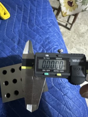
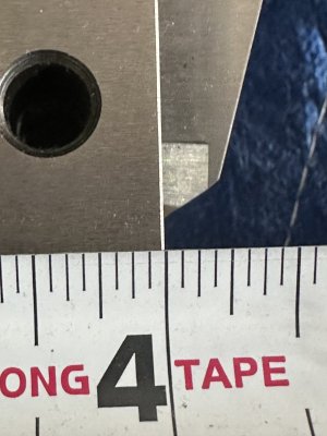
The block and caliper were both in my garage within 12” of each other. The temperature when I took the pictures was 52ºF. The accepted calibration temperature is 68ºF (20ºC), take that information as you may.
The block is a precision 2,3,4 setup block, the edges of the block have been “broken”, the caliper is a Mitutoyo Absolute 8” (I do not own any digital micrometers), the tape is my everyday carry 16’ Tajima, it is not a class 1.
I assumed when pulled from left to right the left edge of the tick line should be where the measurement should land. The reason being, once you cross the left edge of the line you are now into the whole number, even if it is just 0.0001.


Tom
The block and caliper were both in my garage within 12” of each other. The temperature when I took the pictures was 52ºF. The accepted calibration temperature is 68ºF (20ºC), take that information as you may.
The block is a precision 2,3,4 setup block, the edges of the block have been “broken”, the caliper is a Mitutoyo Absolute 8” (I do not own any digital micrometers), the tape is my everyday carry 16’ Tajima, it is not a class 1.
I assumed when pulled from left to right the left edge of the tick line should be where the measurement should land. The reason being, once you cross the left edge of the line you are now into the whole number, even if it is just 0.0001.


Tom
mino
Member
Umm. This is easier than you think it is. While the v2.0 stops are excellent, nothing beats a good old physical reference.However, the problem is actually getting them parallel. Ie, getting both guides set at the same distance. I have the woodpeckers set, and issue (assuming you can calibrate them correctly), is where to set the flip stops on the marker lines. Easy to be off by just a tad. It may be small, but parallel sides are important in cabinet carcases!
I.e. just use a reference piece/off-cut to distance both stops from the back of the rail, one can even make reference sticks that base off the rib surface the saw runs on if wanting within 0.001" accuracy for the PGs. Done.
Eventually, having several "standard lengths" reference sticks for setting up the PGs is about as easy as it gets for those common cut widths. One can even cut them from aluminium profile, if wanting to be fancy..
smorgasbord
Member
I assumed when pulled from left to right the left edge of the tick line should be where the measurement should land. The reason being, once you cross the left edge of the line you are now into the whole number, even if it is just 0.0001.
Thanks! This is with the hook over at the left edge of the block, right?
What if you placed the block against a vertical surface and you did an inside measurement with the tape?
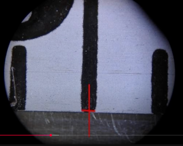
NIST Tape Tunnel:
And a still of them taking a measurement:

As you can see, they split the line down the middle.
tjbnwi
Member
- Joined
- May 12, 2008
- Messages
- 7,351
Thanks! This is with the hook over at the left edge of the block, right?
What if you placed the block against a vertical surface and you did an inside measurement with the tape?
NIST Tape Tunnel:
And a still of them taking a measurement:
View attachment 375980
As you can see, they split the line down the middle.
The reason the hook moves is to make up for outside/pulled, inside/pushed against to compensate for the difference in how the measurement is taken. How accurate the tape remains depends on how much the hook moves.
The closeup isolated above is of what he was calling the zero mark, at no time in the video did they show a close up of crosshairs at the measured mark. Additionally, all of the readings showed slightly strong. If he was going to the center of the line this could explain the strong reading.
Tom
smorgasbord
Member
The closeup isolated above is of what he was calling the zero mark,
Yes, but he was zeroing at something other than actual zero, since most tapes don't have an actual zero. For instance, with the vintage tape, he used 2" as zero. That he used the center of the line, I believe, indicates that is the proper technique.
Additionally, all of the readings showed slightly strong. If he was going to the center of the line this could explain the strong reading.
Since he was going from center to center, that explanation wouldn't seem to be applicable.
In addition, some metal rulers are graduated from both ends. If the intent was to use the edge of the tick mark, then they couldn't share the tick marks from each end, but they do share them.
When I get back to my shop in a couple weeks, I'll try to remember to use a metal ruler doing an "inside" measurement and see where my machined blocks line up.
tjbnwi
Member
- Joined
- May 12, 2008
- Messages
- 7,351
If he did go center to center, his center unless he edge found each edge of the line his center is his best guess by eye.Yes, but he was zeroing at something other than actual zero, since most tapes don't have an actual zero. For instance, with the vintage tape, he used 2" as zero. That he used the center of the line, I believe, indicates that is the proper technique.
Since he was going from center to center, that explanation wouldn't seem to be applicable.
In addition, some metal rulers are graduated from both ends. If the intent was to use the edge of the tick mark, then they couldn't share the tick marks from each end, but they do share them.
When I get back to my shop in a couple weeks, I'll try to remember to use a metal ruler doing an "inside" measurement and see where my machined blocks line up.
I’ll assume he was right and got the centers exact, this means that if he indexed off the left edge of the 0 line (the machine reads left to right) the left edge of the tick line for the number would be correct. I’m pretty certain everyone here knows you read center to center by measuring same edge to same edge of two spaced features. Think framing members, if you hook the left edge of a member, pull to the right, the left edge of the next stud should align to the 16” mark (assumes 16” OC framing).
Tom
Umm. This is easier than you think it is. While the v2.0 stops are excellent, nothing beats a good old physical reference.
I.e. just use a reference piece/off-cut to distance both stops from the back of the rail, one can even make reference sticks that base off the rib surface the saw runs on if wanting within 0.001" accuracy for the PGs. Done.
Eventually, having several "standard lengths" reference sticks for setting up the PGs is about as easy as it gets for those common cut widths. One can even cut them from aluminium profile, if wanting to be fancy..
Are you talking about initial setup and calibration, or setting the width of each cut?
mino
Member
Each cut/setup of the PGs. That is the only sure way to scale/stop accuracy concerns between the two arms as well as between two setups of the arms.Are you talking about initial setup and calibration, or setting the width of each cut?
Use the scale first to make a reference, then use the reference to set both
Last edited:
smorgasbord
Member
Please explain how read from both ends of a shared ruler works using left edges. And why there’s no mark at the very ends.
Similar threads
- Replies
- 6
- Views
- 1K
