The My Shop Cart

UPDATE

I have the torsion box done. I used 12mm BB ply on both sides.

[Pict coming tonight]

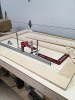
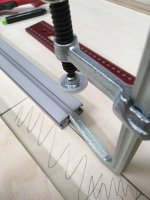
I am now at adding two t-track at the front

13k1002s03.jpg


to hold the SYS-VAC system. I will add another layer of 18mm BB ply on the top only. That way the t-tracks will be shy of 1/16. the first t-track will be flush to the edge to add vertical clamping capability. The torsion box will sit on a rolling cabinet similar to Guy's cart
cart

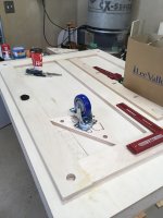
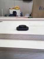
Since it's a rolling assembly table and I made it specifically flat, I want to be able to micro adjust the top for when I move it. So far I found those
01s0810s2.jpg

To adjust from the top. I was also thinking about a threaded rod and knobs mechanism.

Any idea what I could use? It need to be able to support ~400lbs

 
You could just use a hacksaw and cut a slit in the top of those bolts for adjustment ease with a screwdriver.  Or get separate feet with long rods to give you a knob closer to the top of the table.  My concern there might be removing the flush sides that are great if you have T-slot around the perimeter.

Check with McMaster.com for possible feet. Not sure if they ship to Canada or not.  You could fashion your own out of some blocks of wood, T-nuts and feet from McMaster, Home Depot, or similar.
https://www.mcmaster.com/adjustable-feet

Curious where you found that T-track.  I really like the 90 degree clamping options it offers.

neil
 
those t-tracks are exclusive to LeeValley and the feets are from LV too. They do have a slot I mean allen head on top for adjustment
 
Now you guys went and did it.....

You gave me a idea.

You have no idea how dangerous that is  [scared] [big grin]
 
jobsworth said:
Now you guys went and did it.....

You gave me a idea.

You have no idea how dangerous that is  [scared] [big grin]

Wait! What?  [scared]

grrrrrr, I forgot about taking a pict last night.
 
[member=167]neilc[/member]
neilc said:
Mario -

Does that T-track from LV work with Festool clamps?  It looks to be too large in the photos on their website.

Thanks -

They do fit on the thin sides
[attachimg=1]
but not on the large sides
[attachimg=2]
unfortunately... however my plan is to use the top slot (large sides) with t-bolts to hold the SYS-VAC and with festool like clamps on the thin sides for vertical clamping. So it sort out pretty good for my purpose :)
 

Attachments

  • fit.jpg
    fit.jpg
    332.2 KB · Views: 2,507
  • nofit.jpg
    nofit.jpg
    252.3 KB · Views: 2,546
I have been idle on the weekend because I was not happy with the glide feet. The idea of boring 4 holes on the top to adjust the height was defeating the idea of having a perfect flat top, solely to be used for assembly. I discovered those (model A)
01s1901s01.jpg

today  [big grin]. This is exactly what I was looking for, they support 385lb each  [eek]. They will be fixed on the cabinet part and a reses hole will be bored from under the torsion box top, to keep the top aligned with the cabinet. I will also be able to sit a dedicated MFT top on it. Those levelers have a ~5/8 travel.
 
Mario Turcot said:
I have been idle on the weekend because I was not happy with the glide feet. The idea of boring 4 holes on the top to adjust the height was defeating the idea of having a perfect flat top, solely to be used for assembly. I discovered those (model A)
01s1901s01.jpg

today  [big grin]. This is exactly what I was looking for, they support 385lb each  [eek]. They will be fixed on the cabinet part and a reses hole will be bored from under the torsion box top, to keep the top aligned with the cabinet. I will also be able to sit a dedicated MFT top on it. Those levelers have a ~5/8 travel.

Just be aware that the thread pitch on these is pretty coarse. Depending on how precise your level is and whether it matters you might find it difficult to turn one of these little enough.
 
@Micheal Kellough Thanks for the heads up, I totally agree with you. The 5/8 travel works on only 5 full turns. Is it enough? perhaps on a large surface it is. Do you have any experience with those?
 
[member=66597]Mario Turcot[/member] not sure what all you want out of these things. Overall height adjustment can be increased with shims but earlier you said you wanted “micro adjustment”.

Technically, to get the 1/1000” adjustment that implies down here in the Imperial States of America (not sure how fine “micro” is in a metric realm) you’ll need to find a way to turn the screw in 1/100 revolution increments. But, even with a 1/2”-16 thread screw you have to measure out 1/50th turn increments. You probably don’t need that fine of adjustment.

Also consider genuine leveling pads like these
https://www.mcmaster.com/leveling-pads

The little “10-32 nickel plated steel leveling pads” can support 700# each and have 2” of thread for $5 a piece. You’d need to make a mounting plate from 1/4” steel. With a screw that small you’d need to protect it from lateral force but with a long enough wrench you could easily subdivide a revolution into .0001 increments.
 
My apologize, I should have express myself a bit better. By micro adjustment I meant more in the 1/16 increment. There is many hydraulic/air compressed system I could have look at but those aren't accurate, unless you put the money on the table. I understand that it's hard to figure out what I want without having a concise idea of the table and it's components.

In essence you have a rolling cabinet (32" x 54") with a top (36" x 58") sitting on it. The top being a torsion box. The cart will most of the time being used as an outfeed table for the table saw. When I want to make an assembly I simply move it away from the table saw and work from 4 sides. Since my floor have a central drain with a ~1" pitch I want it to stay flat. The torsion itself is not rigid enough to compensate for any uneven surface. That's why I want to be able to slightly adjust each corner individually. I might Not need to make any adjustment at all. But better be happy than sorry  [tongue]
 
Michael Kellough said:
My fault, only skimmed the thread.

Sounds like the floor is the problem. If it isn’t too late you might use adjustable height locking casters.
https://www.amazon.com/WoodRiver-Machine-Leveling-Caster-Mounted/dp/B0039ZIPL4?ref_=fsclp_pl_dp_1

These only have a half inch range...

Those casters look pretty sweet. I already have the casters and like you said floor is the problem. What i am really concerned is to mitigate the torsion box distortion. I will give a try to what I found at LV and see if it keeps the surface flat.

On another note, I will incorporate the Vac-Sys into the table. The Pedal will be in the front center fixed into a little cove like on that thread and the pump will be on a shelf close to the top. Not sure yet about the position. In the event that I want occasionally to move it out of the cart can I use stander air pressure quick connect? The bases have a quick connect on the body but the pedal and pump are fixed.
 
Hi Mario. I'm still not quite sure what you are trying to achieve...are you trying to level the entire outfeed table, or just the torsion box top? I have those levellers you showed in this thread, and as said earlier they are pretty course threads...and they are not a tight tolerance and tend to wiggle a bit...having said that, I haven't used them on a bench with that kind of weight....If you are looking to just level the torsion box I remembered watching a outfeed table build by downtoearthwooder and he used tee nuts and floor levellers that I have also used before, and they don't move.....here's the link if you haven't already watched this series. I think he shows in part how they work around the 10 minute mark..but he drills a hole in the top of his table for access....


Greg

 
The torsion box only. I know a picture worth 1000 words  [scared]

First the torsion box alone will be around 80lb. It's made of 1 sheet of 15mm, 2 sheets of 12mm and 1 sheet of 18mm. In addition I have 2 t-tracks on the long side in the front. The T-tracks are for any clamping needs but mostly to hold and position the vac-sys bases.

On the bottom side of the torsion box I bore 6mm inset on each corners (possibly 2 more in the center). The insets are to keep the torsion box in place where the "levelers" will protrude. I actually have that part figured out, it will not be a micro-adjustment but at least some way to have the torsion box somehow flat.

I'm now at the base where I will have storage on each sides. Once I have the base constructed it will be easier to get a good picture of table.
 
I came to this late and see you have the leveling figured out, but I would recommend bolts and nuts to level the table.  I used that method to level a miter saw on a stand I built a decade ago.  Works well. 
1206a1b9753dab7c0131e14ecd61e7f2.jpg


Sent from my iPhone using Tapatalk
 
[member=53578]travisj[/member] very interesting setup. I took note if ever what I have is not effective,
 
It works well and is relatively simple.  I can’t claim the idea, but I don’t recall where I found it.  Just for future reference if necessary I will add one more photo

57912be142b085eb6b2397545cb3a460.jpg


Sent from my iPhone using Tapatalk
 
More pictures

[attachimg=1]
The above picture shows the frame where the "levelers" (6) will be installed. That from will be on the top of the rolling cabinets. A similar frame will have the wheels on it and will support the whole table.
[attachimg=2]
The above picture shows how the "levelers" will look. The Torsion box and the MFT top will sit directly on the "levelers".

I Hope this help to figure out what I want to achieve.  [big grin]
 

Attachments

  • frame.jpg
    frame.jpg
    293.9 KB · Views: 1,540
  • level.jpg
    level.jpg
    200.5 KB · Views: 1,617
Back
Top